Tuesday 1 December 2015

Aligning Weird Angle Fittings

Sometimes, if you work out Tube and Pipe long enough you will have this problem where fittings are shown at weird angles misaligned with the run. Even if you haven’t encountered this you will at some point so do yourself a favour and read ahead on how to solve it. It is very rare when this happens and starting over your T&P layout again is always an option but you don’t have to because there’s a quick fix.

Aligned fittings

You haven’t done anything different than the usual, but when you place a fitting it comes up at a weird angle and if you try the Change Fitting Orientation command, Inventor will report “0.00” angle and so you don’t know by how much to rotate it to get it to line up with the rest of the run again.

Angles do puzzle me some times but this should be straightforward.

TIP:  The reported angle depends on the type of elbows specified in the route style, how much you drag the rotation arrows or your manually entered angle value. Nonetheless if you get a weird angle and don’t know how to align it then keep reading for a solution.

At this point you might be thinking to use the Change Fitting Orientation command and right away activate Rotation Snap on the right click menu. You will then think of dragging the arrows until they snap to adjacent geometry. Good luck with that! The randomness of getting that command to work has drove me crazy too many times.

You can also measure the angle with All Digits precision active but an almost right value is never the right value.

When I get this problem I unground the component, constrain it, ground it back and then I delete the constraints. Kind of crazy but read ahead why.

 Once you enter Tube and Pipe environment you will get customized menus, layouts and browsers so you the usual commands are not always there and for a reason I might add. While these commands are working you might brake T&P functionality and end up with unadaptive routes or even worse, crashes or corrupted files; none are fun to deal with so keep to the manual or standard procedures as much possible.

One of the missing commands is Grounded status on the right click menu, graphical window or browser. There is a reason for that, and we shouldn’t mess about with it but sometimes we have to and as long as you remember to tick it back on then we are ok.

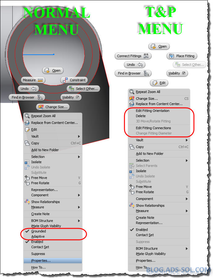
T&P has custom menus, UI layouts and browsers.

Right click the part in the browser or graphical window, choose Occurrence tab and tick off Grounded then click OK.

Ground option is only available on iproperties.
Now you can constraint you fitting however you want it. I usually use the origin planes of the fitting and of the pipe or element right next to it.

Constrain the fitting to fix the orientation

Use the part iproperties to put the Grounded option back on and then click OK. Unfortunately there is no shortcut option to ground components but this is not that time consuming.

Delete the constraints you just created but notice that the part stays put because of the ground status.

And that’s how to align a weird angle fitting.

Later,
ADS.


Friday 27 November 2015

Improving Drawing Appearance

                One thing you have to admit: Inventor drawings can look pretty dull compared with AutoCAD and other packages. Even if you don’t customize your templates and you use the default ones that come with AutoCAD you will get pretty decent looking, good contrasting, and visual appealing drawings.
Choosing the right color for your layers is a difficult task
                Habit and taking things for granted had stopped me from customizing Inventor templates but I am in the process of changing this and improve the aspect of my drawings. When I was editing “Mastering Inventor 2016” there were a couple of files there created by my predecessors with different colors and layers and they looked really good. Slapped the back of my head for not trying it earlier and made a note to start this as soon as.

                There are some things I need to mention before asking you to try this out.

You need to think about what happens to your drawings once finished! Do you export them to PDF, DXF, or DWG? Then you might want to check how they will look with all the changed layers. Some colors will look good on the white/yellow Inventor background but will not be visible on the black background of AutoCAD. While you can print in black and force exports to all black, I would still test this out and discuss it with your colleagues to see if they can remember to tick this option every time or you need to customize their settings and implement some procedures.


Print all colors as black.
Save pdf: all colors as black
You will have to avoid some colors, and no matter how much you like them, some colors you can’t use! I am talking about Cyan, Magenta and Red and that’s because they are used already and they will clutter your drawing making it hard to edit.

Cyan is used to show unattached, orphaned end points, center points, centerlines, etc. kind of stuff and you want it to stick out so you can delete them or drag them to a new attachment location.

Magenta is used to show orphaned dimensions and annotations and you want them sticking out as well and just like above you will want to delete them or attach them to a new location.

                Red is used to pre-highlight geometry like when you hover your mouse over various geometry and elements of the drawing. You will also like to spare this color so that any drawing markup (usually in red) is visible and stands out the drawing, be that printed, pdf, dwf or just plain images.
Some colors you should not use
                Sky’s the limit, go creative and use your wild imagination but test it out for a couple of days. I would not use very bright or high contrasting colors because they tend to wear you down and make you eyes tired.

                With the drawing open click on Styles Editor on the Manage tab and head over to layers to change the display. If you can’t decide open an AutoCAD template like ISO or ANSI and use those colors as a starting point.
Style Manager dialog.

                I only have one recommendation and that is to use grey (any shade) for Hidden and Hidden Narrow layers. It will make it look like wireframe in model making the visible edges stand out.
Use grey for Hidden edges (click on the image to enlarge).
                Hope you fight your habits hard; it’s the only way forward.

                Later,
                ADS


photo credit: photo (license)

Tuesday 24 November 2015

Inventor File History

Continuing my trend on Batman and his bat files (must be one if his invention) I will share some words on how to remove the recently used files from your Inventor history.

Bat files to rescue again.
 If you didn’t know Autodesk has released a tool a couple of years back called Inventor Reset Utility and it supposed to clean the program removing any settings and customization just like a clean install.

This is a good tool to use if you get errors and crashes from Inventor and you need to test a clean session before reinstalling the product. I’ve used this to clear the user history when we moved workstations around but it’s also good for schools, labs, training rooms where people change so often and you don’t need one’s personal settings persistent.

However this will not remove the Recently Used Files on the home page. I have disabled the Home page all completely in Application Options but I still get the recent files if I click on the top left big I icon.

To remove them you need to tweak the registry and even if you know what you’re doing, pressing the Delete key in registry can be dangerous. I mean, we all have one of those days when coffee doesn’t fit in the mug, your allocated parking space is taken, or you’re just tired from being super-awesome the day before.

To remove the registry type "regedit" in the Run command on your Start menu (or press WIN+R). 

Navigate to: “HKEY_CURRENT_USER\Software\Autodesk\Inventor\RegistryVersion19.0\Recent File List” and see your list of recent files. 19.0 is Inventor 2015 internal number and you will of course change it to suit your Inventor version, 20.0 is 2016 and so on.

You will have 500 pinned files and 500 normal files although it’s not necessarily that all the slots are used. Instead of manually selecting and deleting all the key entries you can delete the folder itself and be done with it. Don’t worry; Inventor will recreate it next time you start the program and the home list will be empty.


But better yet why don’t you create a bat file (gotta love Batman) to do this for you while you sit and watch like a proper manager you are?

You can run this as many times you like or have it pinned in Startup to fire up automatically when you log in. Check my previous blog here on how to create a bat file and how to run it at startup.


Later,
ADS

photo credit: <a href="http://www.flickr.com/photos/55883582@N08/10810635493">Batman Arkham City</a> via <a href="http://photopin.com">photopin</a> <a href="https://creativecommons.org/licenses/by-nc/2.0/">(license)</a>


Friday 20 November 2015

Defer Tube and Pipe Updates

I can understand why some of you might find this post boring and hard to read so I have sprinkled it with images from London Underground, mainly Tube Line Service Update and to be honest the first one matches my feeling and situation exactly.

My feeling exactly when Inventor T&P failed to update
                Being self taught is good and bad, and while I find solutions to my problems faster I do tend to be a know-it-all type of jerk that doesn’t take other people’s ideas and remarks easily.

                But what good is all this knowledge and skill if I don’t share the findings? On this premises today I will share a problem I had the other day and the solution I found for fixing this.

                On one of my large plant layouts I had to activate “Defer all Tube & Pipe Updates” so I can do changes to the equipment, foundation and the rest of the plant. Changing a single constraint can take forever on large assemblies especially if that implies updates to tube and pipe. On this particular job I had about 24 runs with multiple routes and even on decent CAD Workstation it can seem forever.

                So I’ve disabled updates on Tue and Pipe and I have started churning away on all the changes imposed by the client. Couple of days later when I finished I have decided it’s time to update some of the pipe routes. I usually work my way one route at a time, fixing connections, dimensions, and adding/removing elements. When I am happy with the results I turn to the next one but before I could even start I have hit a brick wall and couldn’t pass over it.


                I can’t seem to be able to turn off “Defer all Tube & Pipe Updates”. I right click the TP assembly node and choose “Tube & Pipe Settings”, tick off the option, click OK and ... nothing happens. No change of icons, they still are red lightning bolt, and the “Defer all Tube & Pipe Updates” is still marked on the T&P. First thought was to make a new TP asm and recreate the structure of all the Runs which will take a while because they are only 24 if you recall so I wasn’t really keen to do that.

It's like the Matrix deja-vu; keep ticking off and it's not working.


                First thing I tried was to open the T&P asm on a separate window and suppress all the runs, and for that I had to create a new Level Of Detail (LOD). Switched back to my original assembly and tried to change T&P representation to my new LOD and nothing happen. Stuck again I have decided to suppress the Runs from the main assembly, and now turning off “Defer all Tube & Pipe Updates” was working. Feeling that I am getting closer I tried to unsuppressed the RUNS and while they showed up they still had the red lightning bolt icon on them meaning that they might not update and cause problems down the road. I bet this is not just a glitch on the icon and I will have update problems in the future.

LOD not working either.

                I have turned back defer updates and suppressed the runs, then I started to un-supress them one at a time and to turn back on defer updates afterwards so I can track if there’s a specific run or set of runs that cause the problem.
                And I was right! One particular run once unsuppressed it didn’t allowed me to change T&P defer update settings. Using the same procedure I have narrow it down to a single route that was being my pain. Even though the route is displayed in red in the browser, which usually means there are some issues with it (not violations), I can’t seem to find what’s wrong with it. It is simple enough to be bulletproof; 8 lines fully constrained, and yet it’s acting weird.
Source of my problem.
Can't see what's wrong with it.
                Hope you never get the headache I have from T&P and hope you learned something new to try before starting over from scratch. A different solution might be to recreate the Tube and Pipe assembly altogether; just the T&P assembly though, not the routes and all that work, but I will be talking about that on a separate post.

Will end with Quote of the Day:


            Later,
ADS


Wednesday 18 November 2015

Design Data Access Speed

For all my life I have been using Design Data folder on a network server as a mapped network drive. It was only recently that we got audit from Autodesk on one of our large projects and they told us that Design Data needs to be locally and that’s a “must” not a “should”.

All fine  and clear but how do you make sure that your local files are in sync with the network ones especially when dealing with multiple users so that the files are consistent on all workstations.

While you could browse the net a find a dozen free apps that can do that for you, installing and migrating apps it’s time consuming not to mention that installing to many utilities can slow down your computer to a halt.

The solution is to use a “bat” file pinned in the Startup folder.

*.bat files invented by Batman?

What is a BAT file?
A batch file (BAT) is a text file containing a sequence of commands and it’s called batch because it is used to feed the commands to the operating system in bundles rather than needing the user to type one at a time.

In our case we will be using a single command with various arguments to speed up the process, copying the whole folder structure overwriting all but getting newer files only.

Let’s see how to run those commands and how to get help choosing the correct arguments to parse over in the bat file.

On the Start menu choose start and type cmd (you can press WIN+R). We are going to use “xcopy” instead of the plain “copy” command because it will get the full structure of files and folders.


Tip: to see the arguments the command takes type your command and then add “/?” at the end like this "xcopy /?"

The arguments we are going to use are /s /d / y and if you type xcopy/? You will get the following description:
/S           Copies directories and subdirectories except empty ones.
/D:m-d-y     Copies files changed on or after the specified date. If no date is given, copies only those files whose source time is newer than the destination time.
/Y           Suppresses prompting to confirm you want to overwrite an existing destination file.

So we are going to copy the whole structure, no empty folders, overwriting all files, but only copy newer files. The last bit will save a lot of time to an almost instant thing as we will see later.

Start Notepad, either by typing Notepad in the start menu or by using the Start/All Programs/ Accessories shortcut. Type the following:
xcopy "your source folder" "destination folder" /s/d/y  

Click on File / Save and in the Save as type choose All files (*.*). In the filename type a name followed by .bat like: “DesignDataCopy.bat” and choose a local folder to save like my documents or your desktop.


Drag the file from window explorer into Start/All Programs/Start to have it running when windows starts.

As you can see from my demo here, if the local folder doesn’t exist it will be created.


If a new file is added to the source folder when you run the bat file it will instantly be created on local destination. The /d argument makes sure only newer files are copied over speeding it all up.


Of course there’s a catch. If you modify any of the Design Data files you need to manually copy them over to the network drive so that by morning when everybody starts up the new files will be available for them.

This is one more reason to shutdown your computer in the evening and while I restart several times a day just to clear out cache and improve speed I’ve seen others that don’t restart for weeks. If so they need to manually run the bat file to get the updates.

The bat file is here to help... Why So Serious?


Later,
ADS


photo credit: Bat-man via photopin (license) photo credit: 辦公室的新夥伴-小丑先生 via photopin (license)

Monday 16 November 2015

Placing Symbols

Old habits die hard and it’s a constant fight to change them. For all my life when I place a note or symbol I right click and choose continue while I could double click to finish placement.


Start the Leader Note, Insert Symbol, or any other item on the Symbol panel of the Annotate tab, click on the element to detail then move the mouse out and then double click to place it.


I’ve mentioned before that I left the engineering office for about 4 years and changed to inspecting and installing equipment and starting up a couple of plants and while that was really rewarding and helped improved my knowledge I have fallen behind on all things CAD. When I came back to Inventor, Autocad and designing in general I was struggling to find the commands and the menus again but my mind had a mind of its own. After a week or so I found that my hand knew the shortcuts and started commands before I could tell what was going on and before I could realize what the shortcut for that command was. This goes to prove how hard it is to change my habits especially if in a hurry and I switch to auto-pilot letting my mind’s mind work out the details of what to click, where and for how many times.

To further help this habit installed if I find myself placing a note or symbol by using the Right-Click Continue option, which is an automatism by now, I delete it and recreate it with double click. I feel that doing the extra work of recreating the steps to be annoying enough to force my brain to switch tactics and update the habit.

Of course, unlike the right-click continue option which can be used all the time without exception, the double click is tricky and need special consideration in things like Surface Texture where you need to move the mouse out to specify the direction of the symbol and then come back and double click on the original point.

I don’t think this alone will improve speed and get your drawings out faster but changing a lot of these small things can have a good impact so try them out.

Later,
ADS


photo credit: Continue via photopin (license)

Thursday 12 November 2015

Insert Fittings

Inserting fittings is a nice way of adding members without breaking the route and without needing to fix constraints and dimensions.

What I like to do when I have a quick layout to do or a proposal, for which we NEVER have enough time to make it proper, is to cheat and bend the rules as much possible and Tube and Pipe is no exception.


If you’ve finished the route and you ready to place fittings, it’s easier not to drop them in the line, or create nodes but to use the Insert Fitting command.

Once I’ve done my route and proved that it’s a viable solution and that the installers will have enough room to fit it I then turn to starting adding fittings. I am talking about adding fittings like valves, pressure gages, sample points, etc. These are not placed in automatically with the Populate Route command.

If the route is fully constrained and populated it’s a royal pain to add more fittings. Dropping them in your assembly will create new nodes in the route but this process will delete constraints and dimensions and you need to do that extra work to get it back to fully constrained. This is a fully constrained sketch route going crazy with a single place fitting command.

Route going crazy with single fitting placed.

                This is when Insert Fitting comes into place. Use the Place Fitting command to add your parts but before you click to place it right-click in the graphical area and choose Insert Fitting. This will allow you to insert it next to an already existing fitting or between two existing fittings.

Insert Fitting on right click menu.
                If I have a valve to place I find a close nearby elbow or any other populated fitting and I drop it in there, and I keep inserting next to it the rest of the fittings like pressure gages, sample points, etc. I am only interested to show what else will be on that line and to get the BOM quantity and price as close as possible.

                If the fitting to place is already available in the assembly then select it first and use the Place Fitting command. If not, just start the command which will let you browse for a part on disk. With the place fitting command active right click on the graphical window and choose Insert Fitting. You can press Spacebar to change connecting point on the fitting before finalizing the command. Move your mouse pointer next to an existing fitting, and watch how the arrows are displaying indicating your connection and when you are happy with the results click to finalize the insert.

Insert Fitting doesn't break the route.
 TIP: Sometimes you will not be able to place all fittings. No matter how much I try, I can’t place some fittings that have been imported from step or fittings located in library and not in content center. They work fine in T&P but inserting them is not available. What I do is place a fitting that works like a tee, union, coupling etc. first and then drop my valve on top of the tee to replace it. At this point you will also get the rotation dialog allowing you to orient it as needed.

TIP: Make sure that the segment where you are inserting is long enough so that inserting the fittings will not violate minimum length rule.


                If you deal with Butt Welded fittings you won’t need this but if you work with other type of connection like the Socket Weld like I do then there are some limitations. Once the fitting is inserted you need to right click it and choose edit fitting connection. In the dialog you will have two connections, one to the pipe and one to the existing fitting where you inserted yours. Edit the one to the fitting and choose custom distance and enter 0. The fittings by default will engage as per the authoring info which will overlap them.

The other issue is that the pipe will be trimmed to the furthermost fitting last inserted and so you will lose all those small segments in between them and if you need to do a cross section in you drawing it will appear as they are butt welded and the missing pipe segments will also give you less quantity in the BOM and Parts List. This is not a problem for me since we don’t do cut-to-length lists or material lists and it’s only general layouts for installers to follow.


                And this is it; nice and simple to speed up those designs. Would love to see what tricks do you use to speed your work up.

Later,
ADS


Tuesday 10 November 2015

Thread Sort Order

                When a new version of Inventor rolls out and I am doing a fresh install I use a check list of things to do in order to get the upgrade. It’s things like migrating files, importing options and customization files, setting up the templates, etc. But there are a couple of things that I do as I go along and change only when needed. One of the things off the list is changing the threads sort order.

Don't you just hate when the screw opens and the filler or screw gages fall out of order?

                I am a metric guy and while I use imperial units as well and I can think inches just as much as millimetres I still need to change the default thread order. When you create a thread either with the Hole or Thread command I like to have “ISO Metric Profile” as default instead of “ANSI Metric M Profile”. It’s not a big deal to just choose ISO every time but it takes seconds to change it and save my time for something else, like doing this blog.
                First you need to locate your Design Data folder and for that you need to look at the settings of your project. Usually you will have a single Design Data folder for all your projects but you could have more than for your work, school etc. Click the Projects in Get Started tab, on the Quick Access Toolbar (QAT) or on the Inventor (big I top left) Manage submenu. The project can also be accessed on the open file dialog box.


                Expand the Folder Options and check the Design Data field. If it says “Default” then it’s not assigning special location for this and the Application Options settings are in place. Mine says “.\Design Data\” and the “.” in front suggests a relative path instead of a full path and it’s relative to the project located at “C:\CAD” so the location will sum up as “C:\CAD\Design Data\”. Relative paths are good because if I can copy or move the CAD folder without getting missing files and styles error.  If it was a full path and I would copy the CAD folder to CAD-B then the files from CAD-B would look for styles in CAD.


                If the field says “Default”, open Application Options from the Tools tab or on the Inventor menu. On the File tab Design Data filed you will see the location and if it’s not clear or the location means nothing to you, click the browse button next to it and you will see the full location.
                Navigate to Design Data, XLS, en-US folder and open thred.xls. Each thread type sheet will have a “Sort Order – X” cell right at the top which is what Inventor looks at when giving you the default thread. On the “ISO Metric profile” tab change the cell value to “Sort Order - 1” and on the “ANSI Unified Screw Threads” sheet change the cell to “Sort Order - 3”. Save and close the file and if you had Inventor open then you need to restart it. The thread.xls file is loaded in memory when Inventor starts and it will be used while that session is open.


                This will not save you a lot of time by itself but just like tuning a race car it’s the sum of all improvements that will give you performance. A 1% save in time here means nothing but add this up to other 10 small impact changes and you have a fair amount of improved time.


If you don’t use threads all that often then you can keep this in the back of your mind and skip doing the changes but if you find yourself constantly changing the thread standard then go ahead and implement this. It’s only when a new version rolls out that you can decided if this was a good call or not. With the new version installed did you even noticed that the threads are back to ANSI? If you did then you most likely need this change.

                Later,

ADS

Tuesday 3 November 2015

Restructure


Organizing and restructuring is daily job and you need proper tools for that. When I need to move components around there is no better tool than promote and demote.

Restructuring can be tedious and time consuming.
While these commands have nothing new in themselves and you probably use them all the time I would like to share some tricks and tips with promote / demote. The Demote/Promote helps restructure the assembly and you can use the shortkeys Shift+Tab (Promote) and Tab (Demote) or choose them in the right-click menu Component submenu.

Promote/Demote
                As I’ve mentioned before promote/demote is useful in T&P when you have fittings that can’t be deleted and you’re stuck with parts that don’t belong there anymore. You can try and use the DELETE key on your keyboard because sometimes that works, even though there’s no Delete on the right-click contextual menu when you select those fittings.
                At this point you either drag those fittings (multi-select works as well) to a higher level outside T&P where they can be deleted or you demote them to a subassembly that can be deleted afterwards.
                A different trick and different approach that I like to use when doing quick layouts for sale quotes would be to promote existing designs. Consider the following scenario:
I have a plant layout that looks similar to what the new client wants but he has supplied drawing for the plant room so I can’t just save the existing project with a new name. I create the room using the drawing provided by the client and then I place the existing layout that I don’t want/need to change using just a regular place command.
I then select all the components inside the existing project and I promote them to a higher level. The good thing about this technique is that the components will maintain position and even better they will maintain any constraints in between them. This saves time when under pressure and it helps me get quotes out in minutes; these are potential jobs anyway so why waste time on things that might not turn out to be of value.
As soon as you’ve promoted the components you can then delete the original assembly BUT in the dialog window choose not to save it otherwise the assembly will lose its components (promoted).
A different case would be when you have a subassembly more than once in the model and you need to promote its components. As soon as you promote one set of children they will disappear from the other subassembly. There are several ways of promoting the rest of the children up:
1 - If you use Vault or the subassembly is a library or read-only file then this will not work so get to the next point to see a solution. In all the other cases you can open the subassembly in a new inventor session and all you need to do is hit the Save button then head back to the first Inventor session and in the Inventor menu (big I top left) choose Manage and then click on Refresh. Inventor will complain that the subassembly has been updated outside the current session and prompt you if you want to save the current changes at which point you say NO. You can no promote another set of children and use Save on the outside session then Refresh it the current session.
Here’s a small animation.

use Refresh to update changes done outside the current session.
2 - If the subassembly is vaulted, or library read-only then the solution is much easier but takes longer to do. Because we can’t save the file in an outside Inventor session we can’t use the refresh command. The command will work but will not see any updates on the file. As soon as you’ve promoted the first set of children you can then close the assembly but in the save dialog choose NO on the subassembly which should be read-only anyway. As a side note when you use promote Inventor might ask you to check-out the subassembly from vault so you can choose NO in there as well. Now open the assembly again and you will see the subassembly in its original form and you can no promote another set of children.
TIP: If it’s a large assembly you are dealing with, opening and closing it all the time might not be efficient but you can save a copy of the subassembly in a read-write location and use the solution presented at point 1.
Here’s a video of the second solution. I am having a really small assembly but on large files this will not be an efficient solution.

close without saving will reload complete asm.
It is not complicated and I urge you to give it a try. Imagine how much time you will be saving in fixing constraints and dragging components to a similar position. 

Organizing can be easy with proper tools.

Later,
ADS


photo credit: <a href="http://www.flickr.com/photos/12897738@N00/144315128">Metrics</a> via <a href="http://photopin.com">photopin</a> <a href="https://creativecommons.org/licenses/by-nc-sa/2.0/">(license)</a>

photo credit: <a href="http://www.flickr.com/photos/99357189@N00/98009491">wrenched</a> via <a href="http://photopin.com">photopin</a> <a href="https://creativecommons.org/licenses/by-nc-sa/2.0/">(license)</a>