Today I will show you how to change the default monstrous description for steel shapes in
Content Center.
Place a square box section from Content Ceter and see
how the default properties are shown in part list on drawing.

In
order to change the default part number and description we need to copy the
family to our read/write library. Once you do the "save copy as" you need to
change the library view from "Merged View" to "your library" to use the full
extended menu available with right click.That's where you get the "Replace family template" that we will use later.


Head
over to your assembly and place a part from the newly created family. We will
change that part and then use the “replace family template” in content center
editor for that family.
What
we want is to change the default display mode for length from a 3 digit
precision to a millimeter precision and remove the units from it as well.

You
can do that by right clicking the G_L parameter in parameters for the newly
created part. Take off “Units String” and change precision to 0, then go to the
family in content center editor and do a “replace family template” selecting
the new part.

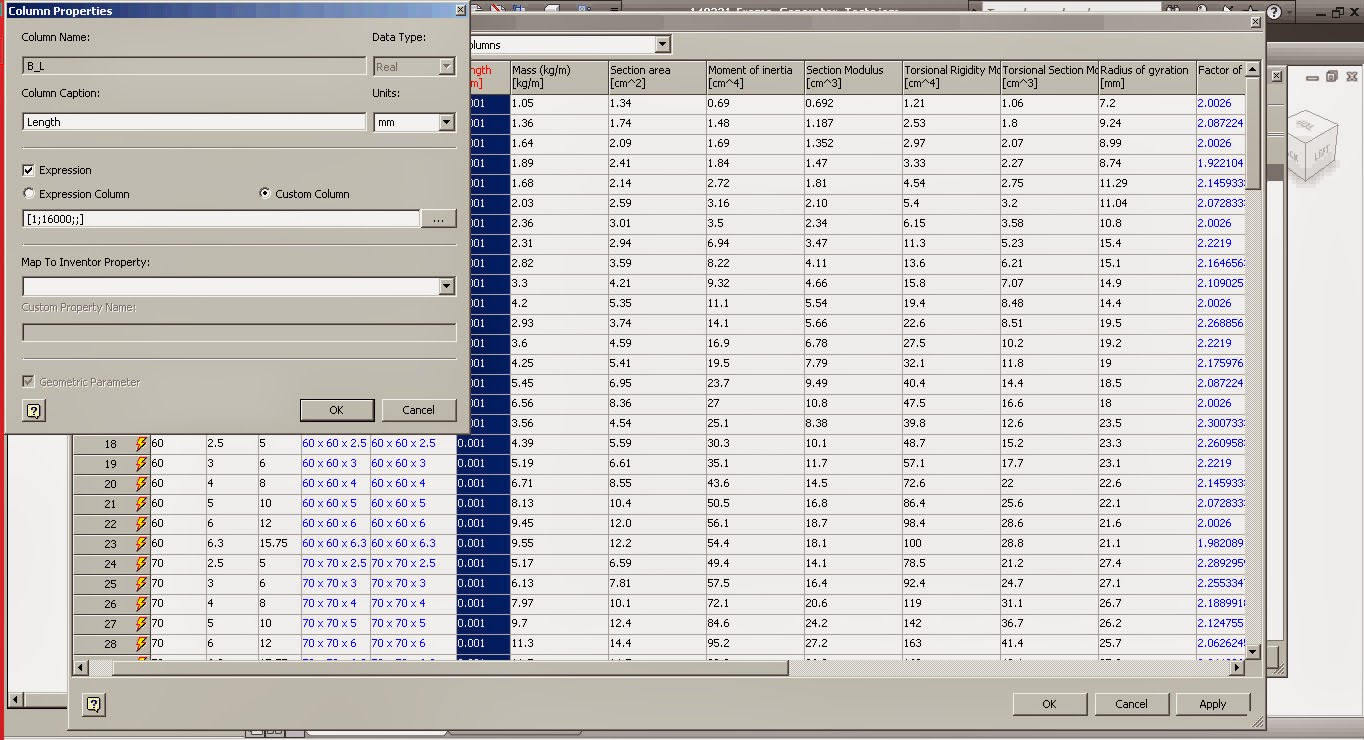
Edit
the family table and change it to suit your needs like changing the “B_L”
column from a 3 digit precision [0.001;16000;;] to mm precision [1;16000;;]. The 16000 in the “B_L” is the maximum allowed
length so you can change it to suit your supplier; we get max 24m length bars
from ours. If you don't care about maximum length and you don't want this to be a design constraint then increase it to something big like 100m.


Now
add a new column “Description” of type “String” and map it to Inventor property
“Project.Description”. Mark “Expression and type the following on the
“Expression Column” field:
"=SHS DIN EN
10219-2" & " - " & {G_H} & "x" & {G_W}
& "x" & {G_T}& "-" & "<G_L> Lg
The
= at the beginning tells Inventor to parse it as an equation and the
<G_L> at the end tells it to get the length parameter from the model. As
soon as the model is created, or modified, Description will get the length from
the model.
Default
length when placing member will start at 1mm up to 16000 mm (or whatever value you have in). Now check
iProperties for description to see the equation at work. Change the size a
couple of times to see it changing.

Unfortunately when
using Change Size from the assembly window it will revert your part number to
default Content Center value so as long you don’t need to change the size you
can change the length from within the part. You go to part parameters and
change the value of B_L.

If you do need to
change the size of the steel shape then make sure you set the part number as
well.
In frame generator as
soon as you use Miter, trim, extent, etc. the length of the part changes as well
keeping an accurate report on the part list.
This
way you don’t need to make a drawing for each component, or use “leader texts”
to get the size of the parts. You have all the info needed in the parts list for manufacturing.

Couple of names used in the industry to get
you started
UB - UNIVERSAL BEAM
UC - UNIVERSAL COLUMN
PFC - PARALLEL FLANGE CHANNEL
RSC - TAPERED FLANGE CHANNEL
AE - EQUAL ANGLES
AU - UNEQUAL ANGLES
F - FLAT BAR
S - SQUARE BAR
R - ROUND BAR
CHS - CIRCULAR HOLLOW SECTION
SHS - SQUARE HOLLOW SECTION
RHS - RECTANGULAR HOLLOW SECTION
Checkout Curtis Waguespack's blog Frame Generator Part Numbers:
http://inventortrenches.blogspot.co.uk/2011/03/understanding-autodesk-inventor-frame.html
Thanks,
ADS
ADS
Ad of course the video:
No comments:
Post a Comment