A couple of friends asked me how I’ve
done the unistrut frame in the image bellow, so today I will show you how to
author structural members to be used in frame generator. I will admit that the
size, part number, stock number or description were not important for this
project. This was supposed to serve as a guide to our installer and I didn’t have
to supply stock size or lengths for it.
I will
admit that the ipart model was downloaded from Charles Bliss’s website and the
only thing I’ve done was to author it to content center so I can use it in frame
generator.
Another
interesting fact was that for this project the skeleton for the frame was done
in Tube and Pipe module with the “3D Orthogonal Route Tool”. It was much easier
than building individual sketches on a skeleton part.
Once
downloaded the parts from Cbliss.com all I’ve done was to verify that the
iparts table was functional and without errors. Then have authored the ipart
and published it to Content Center.
I have allocated
it to “Other” standard so I can find it easier in Frame Generator. There’s no “Moment
of inertia” or “Section area” information just because I wasn’t interested in
doing FEA and frame analyses and if you need them I would suggest doing the
ipart from scratch from a proper catalog like the “Eaton Strut Sections”catalog.
Steps
to author and publish bellow and the published library next.
A while ago I had to dig out a
couple of RAL colors for a project and decided to do them all.
The zipped
ADS_RAL library was done for Inventor 2013 but it can be migrated to latest
version. You need to go to Tools/Appearance and at the lower right corner click
on the gear and use Open Library pointing to our file.
Then
you can copy the colors to any Category on your library.
Today I will show you how to change the default monstrous description for steel shapes in
Content Center.
Place a square box section from Content Ceter and see
how the default properties are shown in part list on drawing.
In
order to change the default part number and description we need to copy the
family to our read/write library. Once you do the "save copy as" you need to
change the library view from "Merged View" to "your library" to use the full
extended menu available with right click.That's where you get the "Replace family template" that we will use later.
Head
over to your assembly and place a part from the newly created family. We will
change that part and then use the “replace family template” in content center
editor for that family.
What
we want is to change the default display mode for length from a 3 digit
precision to a millimeter precision and remove the units from it as well.
You
can do that by right clicking the G_L parameter in parameters for the newly
created part. Take off “Units String” and change precision to 0, then go to the
family in content center editor and do a “replace family template” selecting
the new part.
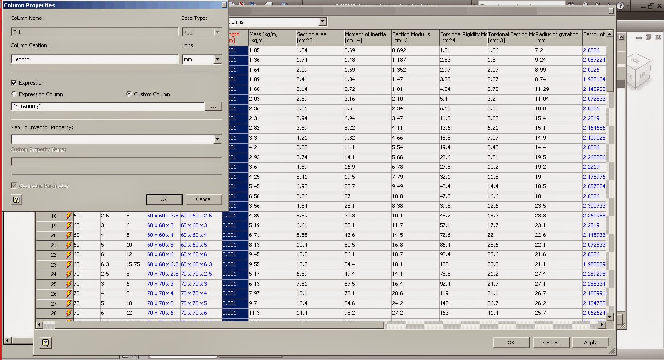
Edit
the family table and change it to suit your needs like changing the “B_L”
column from a 3 digit precision [0.001;16000;;] to mm precision [1;16000;;].The 16000 in the “B_L” is the maximum allowed
length so you can change it to suit your supplier; we get max 24m length bars
from ours. If you don't care about maximum length and you don't want this to be a design constraint then increase it to something big like 100m.
Now
add a new column “Description” of type “String” and map it to Inventor property
“Project.Description”. Mark “Expression and type the following on the
“Expression Column” field:
"=SHS DIN EN
10219-2" & " - " & {G_H} & "x" & {G_W}
& "x" & {G_T}& "-" & "<G_L> Lg
The
= at the beginning tells Inventor to parse it as an equation and the
<G_L> at the end tells it to get the length parameter from the model. As
soon as the model is created, or modified, Description will get the length from
the model.
Default
length when placing member will start at 1mm up to 16000 mm (or whatever value you have in). Now check
iProperties for description to see the equation at work. Change the size a
couple of times to see it changing.
Unfortunately when
using Change Size from the assembly window it will revert your part number to
default Content Center value so as long you don’t need to change the size you
can change the length from within the part. You go to part parameters and
change the value of B_L.
If you do need to
change the size of the steel shape then make sure you set the part number as
well.
In frame generator as
soon as you use Miter, trim, extent, etc. the length of the part changes as well
keeping an accurate report on the part list.
This
way you don’t need to make a drawing for each component, or use “leader texts”
to get the size of the parts. You have all the info needed in the parts list for manufacturing.
Couple of names used in the industry to get
you started
UB - UNIVERSAL BEAM
UC - UNIVERSAL COLUMN
PFC - PARALLEL FLANGE CHANNEL
RSC - TAPERED FLANGE CHANNEL
AE - EQUAL ANGLES
AU - UNEQUAL ANGLES
F - FLAT BAR
S - SQUARE BAR
R - ROUND BAR
CHS - CIRCULAR HOLLOW SECTION
SHS - SQUARE HOLLOW SECTION
RHS - RECTANGULAR HOLLOW SECTION
Checkout Curtis Waguespack's blog Frame Generator Part Numbers:
Today I am going to show you how to
author and publish to Content Center a tube and pipe fitting. The thing I want
to show you is how to push the ISOGEN code and description for the family items
from Content Center.
If you author and publish a fitting,
you will have the same ISOGEN description and code for all the family members. So
the trick is to make it ipart first. That way you can create custom fields that
can be linked to the ISOGEN fields and link back to content center as well.
The default author window is shown below
and if you tryout you will see that you can only put a static value.
Once you make it a ipart and you
add your custom fields you have them as a selection option in the author
window.
After publishing to Content Center
each family member can have different ISOGEN description and code.