I've seen a post the other day on the Autodesk Inventor forum regarding an error that the program throws when trying to replace fittings. The error is "Replace fitting error!"
You will notice if your parts are authored fittings if the thumbnail in the assembly browser looks like a blue tee.
In the assembly the commands "Replace" and "Replace all" are throwing the error. The solution in this case is to restart inventor with the routed systems addin disabled. Once active it picks up on these parts and they can only be replaced with replace fitting command.
A colleague asked me the other day if we can have multi-line iProperties. As far as I know there is only one multi-line iPropertie which is "Comments" on the "Summary" tab. I have been using Comments to add long texts like specs and description of an electric motor, or adding revision notes. He wanted to control the text on the "Project" and force the line return for better visibility in the title block.
The quick solution I've provided was to enter his project text in the comments box where he could control each line with enter and then put a formula in the project box calling the comments like this: =<Comments>.
But then it got me thinking on how else can this be done because it seems the text on all iProperties can be a multi-line one and it's the iProperties window that is's picking up just the last line of text. I didn't wanted to lock Comments and Project with same value so I needed a different solution.
So if you can force the value in a different way it will support multi-line.
First thought was to have 3 parameters for each line of text that he wanted and then have a form called project where he can enter the text on each parameter (each line). Then use iLogic to send all three parameters to Project value like this:
Notice the & vblf & that sends a line feed (enter) command after each line.
This seem complicated having all this parameter and iLogic embedded in the template especially since it's very rare that we need this. Then I've thought that this can be done with just an iLogic rule that can be called and run when needed. Something like this:
---------this was not working, because it didn't retain the ln values ------ ln1 = InputBox("Enter first line", "Project iLogic ln1", ln1) ln2 = InputBox("Enter second line", "Project iLogic ln2", ln2) ln3 = InputBox("Enter third line", "Project iLogic ln3", ln3) iProperties.Value("Project", "Project") = ln1 & vbLf & ln2 & vbLf & ln3 InventorVb.DocumentUpdate()
---------this was not working, because it didn't retain the ln values ------
So we need to add custom properties that can hold the text value of each line like this:
The good thing is that you can have this as an external rule available for everybody instead of embedded in the document.
First time you run the code it will have an empty string, after that it will show the existing value in case you only need to do a small change like typing correction or changing case to upper.
After a couple of searches it seems that Autodesk is aware of this limitation and they are working on fixing it.
Decided to force a video every time, no matter how hard or tiring it might be so here it is:
Branch fittings anyone? They are
a weird one I’ll tell you that, especially the authoring part for routed
systems.
I needed flow meter fitting
authored and ready to drop from the library so I downloaded the .sat part from
GF’s website and saved it in ipt format.
Before you go to authoring the
part you need to modify it a bit.
1. First you need to add a mating
point where the fitting connects with the pipe.
2. Then you need to create the
pipe axis. For this I have first created a sketch where I have drawn a circle
being the O.D. of the pipe and constrain it tangent with the mating point.
Then you can create an axis that
will go through the center of the circle perpendicular to the sketch plane.
3. We also need to create a
cutting profile if we want the pipe to be cut out by our fitting.
Use the pipe axis created above to
create a plane parallel with the top face of your fitting. Add a circle or
project the existing pipe ID edge as your cutting profile.
Now you can go to authoring tube
an pipe.
On the Type drop down list choose
“Branches” and set 2 the number of connections.
My fitting is a special size 1.26”
flanged fitting so first End Treatment is Flanged, of size 1.26in. Use the
upper circular edge for your Connection Point and Axis.
The second Connection is of type
Welded and because it’s a one size fitting I will have M150 in both Min, Max
Size.
Use the work point created for
the mating point and the work axis for the pipe axis. Finally select the circle
on the cut profile sketch and mark if to cut the mating pipe or not.
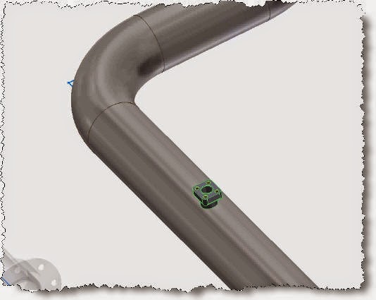
Click ok and turn the visibility
off for all work features and sketches. Here is the end result once you drop the fitting on top of the pipe.
I have managed to do a post every week (sometimes more than one) but haven't been able to make videos so I've decided to do one for this post.Here it is:
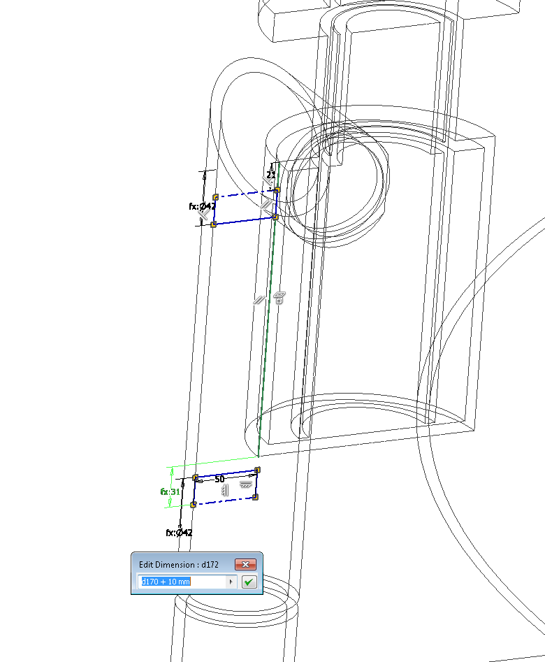
If you work with routed systems
you might have notices how hard it is to pick dimensions and edit them, because
most of the time they are too close to routes.
If you start the dimension
command first ( I use “d” key shortcut) from the Route/Constrain/Dimension menu
it will only pick dimensions. So when you click around the dimension you want
to edit it will open the edit dimension dialog.
Of course this works on all
sketches and drawings not just routed systems.
Every
once in a while I need to change the model but some features and sketches
become uncomputable because dimensions flip unpredictable. I wish there was a
way to over-constrain the sketches but I haven’t found one. It’s especially
annoying when placing ifeatures with driven position and size.
So
typical solution is to delete the flipped dimension, drag your sketch entities
to the correct side and dimension again. But what if the flipped dimension is
used as a reference for other sketches and features?
One way would be to export the
parameters as xml, do a search replace for old/new dimension and import it
again or use the solution bellow.
Edit your sketch, select the
dimension and change it to “Driven Dimension” either with right click or from
the menu Sketch/Format/Driven Dimension. You can copy the formula for your
dimension first if there is one so you can paste it later.
Drag the geometry on the correct
side and select the dimension again. Change it Normal Dimension and edit the
value. Paste the formula or value if copied on the original.
This way you don’t mess the
parameters for referenced files.
Another post on incrementing tags for
valves, equipment and instrumentation on P&I D done with AutoCAD.
I hate repetitive boring jobs so I much
rather spend a couple of hours researching for a quicker, faster solution
before doing the mundane.
In this case I wanted to automate the
assignment and incrementing of tags numbers for valves, instrumentation and
general texts in electric schematics.
You really need to open the webpage to see
the full capabilities of this routine but here’s how I've used it.
Fits, I've selected all my instrumentation
and added “000” to the tag number so that the function can pick it up as a
number that needs changing (incrementing).
Type numinc to get the options window.
We start all instrumentation at 500 so I
have 501 for my fist number with 1 as increment. You can type it anywhere in
the prefix, middle or suffix as long as you tick the correct section to
increment bellow.
I have then clicked the “pick on screen” to
select the block type that needs changing, selected my block and clicked OK.
At the command prompt type “R” in order to
replace an existing value, in my case “000”. Click on each object that you want
modified in the exact order you want it incremented.
I have placed a temporary valve tagging
block and started the numinc again. I have used “V” as prefix and 101 (we start
all valve tags at 100) as middle incrementing middle by 1 each time. Select the
temporary valve block with “pick on screen” for objects to modify and click “OK”.
I haven’t used “R” because I need the
program to place new blocks on the fly just like in the image bellow.
Totally love Lee Mac’s website and if you
find it useful, it won’t hurt to donate especially since he keeps his source
code free. It's nice to see the code that does all this magic.