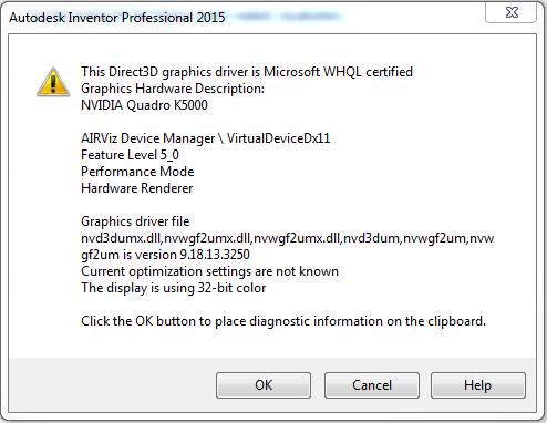
I had a weird one the other day
and I‘ve decided to share it with you in case you run into this. I was going along
just fine until this came up:
“Graphics Driver Error
Failure to create the graphics processing capability
necessary to display the geometry requested. Please update your display driver
to the most recent version”
Well now... my driver seems fine, all good and tested so what are you on about?
This
happen when placing fittings while doing runs in Tube and Pipe environment and
at this point the routes went black, (more like a silhouette shadow) and after
clicking ok or escape a couple of times the place works fine and when finishing
the command they all turn regular color again.
Called
IT and logged the issue but decided to investigate myself and I found the problem.
I have been playing with the environment lighting style, and
selected “Use Image Lightning” on my “Two Lights” style. I wanted to use “Empty
Lab” image lightning because it seemed better for the type of layout I was doing.
Maybe this is too much for my K5000 GPU and as soon as I took off image
lightning, everything went back to normal.
Just
had a couple of more crashes and corrupted T&P assemblies and I’ve decided
to share the pain, or is it the fun that I am sharing, don’t really know
anymore. I seem to confuse them all the time.
As
mentioned before, if you are working with T&P environment and you seem
to be getting weird results it might be because of a corrupted T&P
assembly. Some of the symptoms are:
-Importing styles reports
success but not styles are present (or have been imported).
-Styles have gone missing in
styles editor (none present).
-Changing styles will not update
routes.
-Style not persistent in all
runs/routes (looks different, gap, size, appearance, etc.)
-Cannot place fittings, onto
routes or freely.
-Any other anomalies or
behaviours different than usual T&P work process.
The typical folder
structure for T&P is:
1.MAIN ASM
1.1T&P ASM
1.1.1Run1
1.1.1.1Route 1
1.1.1.2Route2
1.1.1.3ETC.
1.1.2Run 2
1.1.3ETC.
You’ve got a couple of choices here and you can:
-Use a previous version in
OldVersions or in Vault history. Not really an option for those that don’t use
vault and the problem might be older than the backups in OldVersions.
So now what? In
short you need to create a copy of the T&P assembly, or just the runs, or just the
routes, depending on where the problem is.
STEP 1:
No matter what you do the first step is to create a new context for the T&P
ASM.
Option 1:
Create
a copy of Main ASM under a different name and that’s because we might still
need the original one to save/update original files (will get back to it in a
second).
Option2:
Create
a new asm , place Main ASM in it and promote all components except T&P
assembly. This is to maintain constraints and relations between components.
These options are necessary, and
they will create new files for the new T&P asm, as well as all the runs and
routes. I would use option 1 because with promote/demote you lose constraints of the main asm, as well as any modifications in the asm, like parameters or
representations (view, position, lod)
STEP2:
Recreate the T&P asm in the
new context
Option 1:
- Use pace component and place
the original T&P assembly here.
- Right click on it and select
“Make Adaptive”. This will create new files (copy) adaptive and activated as
T&P type editable files. Make sure you have “Make all runs adaptive”
ticked.
You will lose all references and
included geometry for your routes but at least you will have all files created
as new in the closest possible configuration to the original one. It’s just a
matter of re-constraining the routes, and re-projecting your references with
“include geometry”. If the T&P was corrupted sometimes in the copy process
it takes the errors with it as well so check next step.
Option 2:
If you still have problems with T&P
then you need to repeat Step 1 and instead of placing the original T&P:
- Create a new T&P from the
Environment/Begin/Tube and Pipe.
- Save main asm (top level)
- Not necessary but I do go back
inside T&P and delete Run1 (automatically created)
- Use place component and place
the original runs. They are asm files as well and they look like this: 150122-05.Run01.iam
- Save main asm (top level)
- Back to T&P and right
click “Make Adaptive”
- Repeat for all Runs.
Option3:
If
you have problems with one of the runs, then:
-Recreate
Step1:
-
Start a new T&P environment.
-
In the newly created route use place component and add all the fittings and
routes in the original run.
-
Do this for all runs.
-
Save the main asm (top level)
-
Make them adaptive.
This
is the longest and most frustrating, repetitive, time-consuming option but it’s
here just in case some runs go bad.
Things to consider
if you experience corrupted files lot of times:
-Keep the T&P template in
Design Data folder clean. Don’t add any styles to it, don’t edit it, this will
help you when migrating to newer versions of Inventor. Have the styles exported
as xml and import them when needed in your current project. Don’t import them
all, just the one you are going to use
-Make sure you have all
libraries attached to your project.
-Keep styles consistent with
Content Center (no missing libraries, corrupted family tables, proper authored
pars, etc.)
-Don’t have long folder paths.
T&P as well as Design Accelerator and FEA tend to create long file paths,
so keep your projects as close as possible to root drive so you don’t overpass
the MS Windows limit of 256 characters.
I haven’t
finished with all the tube and pipe posts, just got sidetracked with authoring
fittings and decided to share the problems and solutions found along the way.
Can’t remember
if this has always been a problem but in 2015 even though you follow all the
known steps and procedures you don’t always end up with usable tube and pipe
fittings. I have been publishing a couple of fittings for a new route style and I found that you either end up crashing inventor or they can’t be
found while browsing on the new T&P (tube and pipe) style dialogue.
First thing I
recommend is to check the pipe and fittings end treatment. In my case the same
pipe can be but welded or socket welded while the fittings (elbows, tees) can
only be socket welded or but welded. So I used jointed on the pipe and jointed
on the fittings no matter what type of connections they really are. On the
fittings use different engagement distances to differentiate between socket and
but welding. This is to avoid warning message every time you edit the style
about non matching end treatment connections. Remember I don't keep any styles inside the T&P template but import the ones needed when starting a new T&P assembly.
We don’t use
ISOGEN exports but I like to have it setup just in case we will ever need to.
In my ipart table I have setup ITEM-CODE and ITEM_Description columns that I
have used in the tube and pipe authoring dialog. The only column that needs to
be on the ipart table is ND (nominal diameter) that I use as key when
publishing to content center and that Inventor uses in the tube and pipe style
setup. You can add this column while editing the ipart in the custom tab or you
add it while editing the ipart table with excel. I like excel because it can
contain any information you can think of without messing the ipart table. As
long as you leave an empty column (actually first cell of a column) between the
info you want in the ipart and the rest of your data, you can have any info you
like. Formulas, graphs, images, even catalog pages from the manufacturer.
Setup the ISOGEN
properties and engagement correctly but leave the end treatment to jointed.I don’t have a shoulder for pipe limit stop but I have created planes
that will serve as my engagement limit in the author dialog.
You need to understand that socket and but weld “End Treatment” filter
on the library browser while setting up you style, will not get you these
parts; “jointed” will. So don’t filter by socket or but weld, as you will see
later I use Standard and maybe Material as my filters.
After you finish publishing to content center you will find that a “Designation” column is added
automatically by Inventor and it’s linked to the part’s “Design Tracking Properties: Size Designation” which is of type
string and can be edited but not in the iproperties window (code or else).
It seems this is used only for content center
stored parts and represents a “succinct
user-friendly universal way of providing a name for the component represented
by a row in the table”. This is copied from an old pdf I found on
iproperties and VBA by Sean Dotson at AU2014. Most of the times you will have a
description of the item like “d10 x 1 – 250 Lg” and it doesn’t need to be
unique. I think this has been left over and obsolete so I would just ignore it except when it gives you problems with tube
and pipe style as it did to me.
It seems that it can be accessed
as “Content Library Component Properties” as well:
Comments: Size Designation: String (VT)BSTR),
Editable, No UI, Succinct, user-friendly and universal way of providing a name
for the component represented by a row in the table.
Why have I gone
to such length and dig out old posts and manuals to find the info on
Designation? Because I found it to be the source to my problems, and there’s no
logic to what my problem is as well.
I've been having
this weird problem with tube and pipe styles. After I author and publish a tube
and pipe fitting it won't show up for selection in tube and pipe styles until I
edit the family table and delete the
designation values. I don’t edit the column formula just select all values
in this cell and delete them. Because the column is an expression
the cells update automatically to same values but now the family
appears in tube and pipe style editor.
As soon as I delete the designation
values, the family appears in the styles editor as you can see in the animation
bellow, where I have 2 inventor sessions running at the same time.
In the style
component browser if you expand your part you will see individual members as long as you have a unique individual
stock number. The members are shown by stock number and AU explanation was
that part number can have custom lengths so not suitable to use here. I don’t
pick individual components just the family when setting up the styles.
Hope you never
run into these problems but if you do try deleting the designation values and
see if it fixes it. Next week I will
share a couple of excel tricks for retrieving data from other spreadsheets with
vlookup match and error handling like when value not found returning #NA so
check back. Hopefully I will finish the rest of Tube and Pipe tutorials. I will also share this elbow and excel as separate file (it's embedded anyway in the ipart).
I've seen a post the other day on the Autodesk Inventor forum regarding an error that the program throws when trying to replace fittings. The error is "Replace fitting error!"
You will notice if your parts are authored fittings if the thumbnail in the assembly browser looks like a blue tee.
In the assembly the commands "Replace" and "Replace all" are throwing the error. The solution in this case is to restart inventor with the routed systems addin disabled. Once active it picks up on these parts and they can only be replaced with replace fitting command.