Friday 21 October 2016

Drawing layers

                Do you use layers in Inventor drawings? Or do you consider them legacy, obsolete, pre cretaceous kind of animal?

Add caption

Last week we looked at showing hidden lines for buried components and now we look at a different method for doing that but with the additional benefits.

                When detailing pipe routes you can use the “Include Route Centerlines” command but if that view is a detail, section, cropped view you end up with a lot of extra lines. You can use this method to clean them up as well.
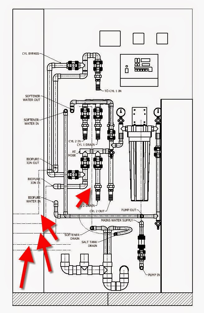
Include Route Centerlines, adds more than visible.
               

                Another good example is the worm gear bellow. I have an M10 hole on center and I can’t really show it properly. Top left to bottom right I have hidden lines view, normal view, hidden break out view, normal breakout view and yet not of them looks good enough.

Top left - Hidden Lines, Top Right - Normal,
Bottom Left - Hidden Break Out, Bottom Right - Normal Break Out

                What I tend to do is turn the hidden lines on for that view then edit the layers, where I turn off every one of them except Hidden and Hidden Narrow and save the style. Now I only have left the hidden lines which makes it so much easier to delete the extra stuff.
               
Turn layers off to help your selection.

                TIP: On the edit layers dialog window you can SHIFT select them all and when you click the light bulb the visibility changes to all at once.

                TIP: It’s much easier to do a window selection and select all and then hold down CTRL and deselect the view, and other curves that you need keeping. You can then use the Visibility on the right click menu to turn them off at once.

                And there you have it. Hope you’ll put this to good use and give layers a chance ; they are not used just for AutoCAD exports only.

Later
ADS


photo credit: Eugen Naiman layers (license)

Thursday 13 October 2016

Drawing Hidden Lines

In the drawing have you ever needed to show components buried down below?


I didn’t have a lot of time this week for blogging but I forced myself to wake up early today and write a couple of words on this trick I use quite a lot. Will try and keep it simple for now and will do a follow-up next week on layers and how to leverage them to your advantage.

                A lot of the times I find myself in need to indicate components that are not visible unless you change the view to hidden lines. That can be daunting for untrained eye to look at and it will clutter the drawing so I tend to avoid it if I can.
               
For example take a look at the vessel in the image bellow. Turning the view to hidden lines would have made a mess out of it with no way to identify what’s what. Showing just the legs in hidden lines makes a huge difference.

Hidden lines accentuate design.
To show a component you need to find it in the browser, right click, and choose "Hidden Lines".

Enabling hidden lines

As soon as you set hidden lines on you get a message saying "Dependent vies styles will become independent”.

Changing the view message

Sometimes the “Hidden Lines” menu will be grayed out and that is because your view has linked design view representation. For that you need to edit your view and tick the “Associative” box off as bellow.

Associative off on view properties

A new option is needed here besides “show hidden lines” and that should be simply “show” which will turn the model visible (in dotted lines because it is underneath in the background) without its internal geometry. I need to indicate the component in outline, not the whole geometry but that’s for a latter post.

Next new feature?
   
Take a look at the drawing below. The drain header is visible and I only need the outline body; normally we show all runs in hidden lines but this is just a sales proposal and I couldn't be bothered. This shows just enough info, eliminating clutter and accentuating design.

Way better, isn't it?

Later,
ADS


photo credit: Max Garçia Metallica (license)

Friday 7 October 2016

T&P Hoses P2 - Documenting Hose Lengths

How do I show hose lengths? How to document hoses? I need to document cut lengths, swage distance as well as overall lengths, so how to do that?


                Last week we covered BOM structure for hoses and I’ve showed you how to mark them as single items in BOM / Parts List. This is useful if you don’t’ manufacture the hose and you don’t need to show all the sub-parts individually.

                But what if you need to show those dimensions and send the drawing over to whoever is going to manufacture it; assuming it’s not a standard stock item.

                Hoses are created as a subassembly in tube and pipe and you get the route, the sweep part and the connectors (depending on style settings) in one single assembly.

Hoses are created as assemblies

                Unfortunately the info is not at the assembly level and it can’t be exposed when changing BOM structure to “Purchased” or “Inseparable” (check my previous post here). All the info is created in the hose part (the one containing the sweep).

                If you open the hose and check the parameters window you can find a couple of parameters defining the various lengths for the hose (they are exposed as custom iproperties as well.)

                If you open the parameters window here’s what you will find:
PL - Pipe Length (hose in this case)
RPL - I believe this is "Rounded Pipe Length" (hose in this case)
OPL - I believe this is "Overall Pipe Length" (hose in this case)
ROPL - I believe this is "Rounded Overall Pipe Length" (hose in this case)

Parameters exposed to iProperties.

If you have connectors each end (like I do) you will notice that the sweep sketch is made from a spline and 2 straight lines (swage distance). Measuring the spline and the individual lengths you will get PL(hose length) which is then rounded to the nearest increment (changeable from the T&P route style) and you then get RPL (rounded hose length).

Rounded increment is declared in the Route Style

OPL (overall hose length) you get by adding the connector lengths to the PL (hose length) and just like above when you round this to the nearest increment you get ROPL (rounded overall hose length).

                If you need this info in the Parts List you need to add these custom iproperties manually by editing the drawing table. However if you marked the hose as “Inseparable” or “Purchased” the info will not show up.

                In both cases you can add a Leader Line and use the “Custom Properties – Model” to show these on the drawing.
Use Leader Lines to document the various lengths
                Here's a short animation of the process.


Later,
ADS photo credit: Garden hose (license)

Monday 3 October 2016

T&P Hoses P1 - BOM Structure


Do you include hoses and flexible tubing to your design? Are you thinking into taking your products to next level by adding this info to your design?


While we use them in our plant layouts we don’t really document them on the drawing but nonetheless there are some good practices as well as tips and tricks.

Will keep this simple and split it into separate blogs and for now the question is:

How can I show a hose assembly as single part?

We are not hose manufacturers so it would help to see the assembly in the Parts Only section of the BOM along with all the fittings, valves, conduits, all parts really to be purchased.

This needs editing the BOM and changing the “BOM Structure” field to one of these 2 options:

- Mark it as “Purchased”

-Mark it as “Inseparable”

For all my life I have been thinking about “Inseparable” items as welded, casted, glued, press fitted, riveted kind of items but it’s really just a way of grouping several parts in BOM.

“Purchased” it’s what I’ve been using and it’s a nice way of merging multiple parts as a single item. Think of skids, tanks, etc. or any assembly which you vendor has sent over and you consider that a single purchase / single item.

The advantages of keeping it or importing it as assembly rather than single part is you can play with Level Of Detail (LOD), Design View Representations or show different positional representations.

 In the Structured tab you can still expand and collapse it (if show all levels is active), edit the iproperties but now it shows up in the Parts Only section of the B.O.M.

At this point should mention that if you want to show the child components of the hose assembly you will change the BOM Structure to “Phantom”. This will promote the children and hide the subassembly; I use this all the time to group things together for less constraints, improved pattern, etc.


Changing Bom Structure type.
Later,
ADS


photo credit: Steel-braided hose (license)