Thursday 29 May 2014

Placing Fasteners in Inventor

A couple of words on placing fasteners and Cointent Center items in general. I decided to make the post after seen a couple of colleagues struggling to place and constrain hundreds of items by hand. Hopefully this will get them started in the right direction.
For speed I have added the most used fittings and fasteners to favourites, that way I can place them without actually opening Content Center.

In the assembly environment you can switch from model to favourites and have them all accessible; you can even use drag drop.
Inventor uses imates to constrain the fittings and they are really half constraints declared on the part that become active in the assembly. Based on your selection Inventor will try and match the best constrain for you, cylindrical, mate, insert, etc. provided that the imates were declared on the part (sounds really complicated).


As long as the holes were made in one feature or made with a pattern, Inventor will pick them all up and will try and place your item on all of them. I suggest using patter because they will become associative and will automatically change the number of instances based on the pattern. You can use suppressed or independent feature on patterns to get the proper number of instances. In the video, on the last example I have the middle hole suppressed on the pattern of the plate.
In one example I have a washer under the bolt so the insert imate will not pick the patter on the part. In there you can select the hole surface first (cylindrical constraint) and then the face of the washer (mate constraint) to activate the pattern automatically.


If you need to constrain a lot of Content Center items together you can use the ALT button on your keyboard. Select one component and the imates become visible, hold down ALT and click-drag the desired imate constraint to a similar one on the other component. It should snap automatically in place.

Watch the video as well for a better understanding of the concept.

ADS


Thursday 22 May 2014

Inventor Fly mode with Space Navigator

Had a long week at work and on top of that I have reinstall win and all software so this post comes late in the day but still Thursday so hope you are not too disapointed.

I have been using a 3dconnexion space navigator for years and I wouldn’t think of doing Inventor and CAD in general without it. I still remember the “F4” spin command and I use keyboard shortcuts all the time, the multi character (AutoCAD) type, but my space navigator comes naturally.
There is an issue thou and that it’s running out of zoom. If you want to do a fly out type of navigation you can’t with the current Inventor settings and apparently it hasn’t been fix even in version 2015.
Scott Moyse has been reporting this for a couple of years and he even created an idea in the Autodesk Inventor IdeaStation and he has a fix for it. You do need to edit the windows registry; I don’t suspect anyone crashing windows from this but do make a backup of your registry file before.

1.       First, go to Inventor/Options/Display tab and mark down the current settings in the 3D Navigation section.
Here are my settings:

2.       Close inventor.
3.       Go to Start/run and type regedit
4.       Navigate to HKEY_CURRENT_USER\Software\Autodesk\Inventor\RegistryVersion14.0\System\Preferences\Display
(I am using Inv 2010 which is Version14.0, yours will have a different number depending on Inv version)
5.       Double click on Viewing Command Options and change the Hexadecimal Value data to : 21
6.       Click ok and close the Registry Editor.
7.       Open Inventor and check to see if the settings in Inventor/Options/Display/3D Navigation are still the same, modify them back if they changed.
8.       Try out new navigation mode by activating perspective view on a model.

You need to move-release the space navigator in order to refocus-readjust zooming distance. You can’t do it in one smooth continuous movement.
The next trick I am going to share is adjusting the perspective view angle. While in perspective mode if you hold down CTRL+SHIFT+WHEEL UP/DOWN you will change the perspective angle.
                Mine is set to maximum for screenshots and presentations.
                This is how it looks with minimum perspective angle:


                 And this is how it looks with maximum perspective angle:


If you find it useful and want it implemented then go to the Idea Station website and vote for the change.

ADS

And the video of course:


Thursday 15 May 2014

AutoCAD Overkill command

I have been doing a lot of 2d to 3d from AutoCAD to Inventor so I will share another useful command to know. The command is called overkill (dreadful name) available from the Express Tools menu so you need to have that installed before you can use it.
                The command button is actually called “Delete Duplicates” (much better name) and it will clean up overlapping geometry deleting duplicated and unneeded objects.


                The front view of my AutoCAD drawing contains 11388 elements and I will try and clean it up a bit before copying it in Inventor.
               

                Type overkill or click on “Delete Duplicates” and mark everything on the “Object comparison settings”, this way you delete ignoring elements on different layers, different line type, colour, line weight, or plot style. I like to set numeric fuzz to 0.001 because I don’t normally make anything less than micron precision, but first check your drawing units and make sure you are on mm.


                I have been left with 3544 elements now after the clean up making it much easierw to import it in Inventor.


ADS.

Thursday 8 May 2014

AutoCAD selection tools


Let me share a couple of words on AutoCAD selection tools. I have been in quite a few engineering offices and for some reason these commands are not used properly or even at all. For example I haven’t heard anyone using temporary tracking “TK” command no matter of the AutoCAD flavor and user background (electrical, mechanical, P&I D)
                Let’s review the standard ones; single click selection or window selection. Single click just adds to selection and holding shift removes from selection. Window selection can be left-right and right-left having different effects.

 Right-left selection (displayed with a green shade inside the selection window) will select everything included in the selection window plus all intersected by the selection window.


Left-right selection (displayed with a blue shade inside the selection window) will select just the things inside the selection window.


A lot of the times though your elements won’t fit a rectangular window so you can do a polygon selection.
This selection can be “WP” window polygon or “CS” crossing polygon or “F” fence. WP will select just the elements inside your polygon.


CS will select elements inside and everything your polygon intersects.


Fence will select jus the elements intersected by your polygon.


When you use WP, CP or F and you picked a wrong point for your polygon (eg. You have osnap on and it snapped to existing geometry) you can type “u” (undo) and it will undo the last segment of the polygon (this can be done multiple times to undo several segments).

If you accepted your selection too early, picked wrong base point or you realized you need to add stuff to your selection then “ESC” your command and start it again. Then when prompted to select objects type “P” previous which will select your elements again.

Fence is especially useful with trim and in the image bellow I have used it to cut the yellow lines in between the circles.


Bellow I have used fence again to extend the yellow lines up to the blue outside circle.


Let me show you track “TK” command now. I want to copy the bottom circle up 200 and left 200 in one operation.  When prompted for location on copy command type “TK” and start tracking from inside the original circle left (or up) 200 and then in the other direction.
In this example I will copy the circle 200 mm from each edge of the square. You can use “TK” for the copy point and paste point.

All these commands are available with any of the modify commands (trim, extend, copy, move, rotate, stretch, etc.)
Watch the video for a better visual understanding of these commands.

ADS
And of course the video:


UPDATE 09-Jul2014: Check the new post with a bigger selection list here

Thursday 1 May 2014

Inventor Auto-Constraints


Today we are going to cover automatic constraints as well as tips for importing AutoCAD geometry in Inventor.
I use automatic constraints quite often whenever I am using projected edges and surfaces. I work with fairly large assemblies (<15 000 components) and I don’t like Inventor computing more than it should do; therefore I never use “adaptive” sketches and parts, and I always beak the link of any projected edges.
In this example I will import part of an AutoCAD drawing so I can make my building layout and because I use copy/paste instead of the import dialog I need auto-constrain the geometry before extruding or revolving sketches.


Once you cleaned up the drawing for irrelevant entities you can use the import function in the part sketch or just copy/paste from AutoCAD to Inventor sketch.
When you import the sketch you have the option to “Constrain End Points” and to “Apply geometric constraints” but on big layouts with lots of entities it will take a considerable amount of time, quite often ending with Inventor crashing. I suggest you keep you sketches small and clean up the AutoCAD file before import, like deleting overlapping lines and moving all elements to one layer. Brake out the import in separate operations or copy/paste smaller bits for better results.


Either way you choose to get the geometry in Inventor I suggest making it block afterwards so you can drag them around and constrain it against origin without having parts of it fly out.


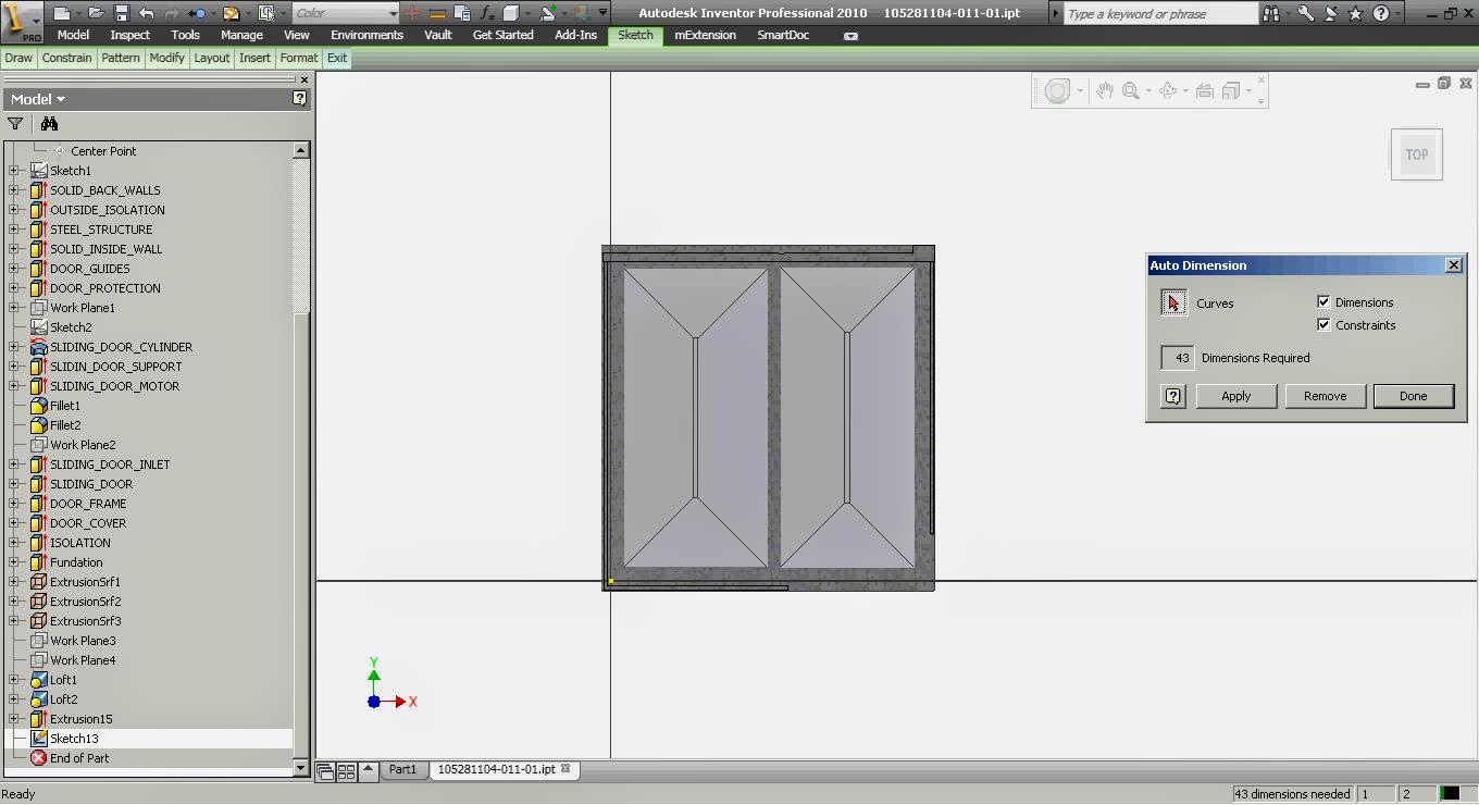
Go inside your block now and use the auto-dimension option (sketch/constraint menu, mark just constraints) to close all open loops. You could use sketch doctor to close all loops but a lot of the time it tends to connect adjacent points messing out the geometry.
Same thing when projecting existing geometry, after you brake the links use the auto-dimension (keep marked just constrains) to connect redundant points and open loops. Bellow you have sketch status before auto-constraints (43 dimensions needed) and after auto-constraints (25 dimensions needed). Some people like to use the lock constrain on all geometry, I like to make it a block to keep it all together; that way I can still move it and connect it to the origin.


ADS

And the video: