This is last
part of the series, covering how to publish dumb parts to Content Center. Now
you know where to get
parts on the internet, how to create work features,
and how to author
empty parts. This is all neded info before we take the final step.
Quite
simply publishing dumb parts as a family in content center is based on the
ability to create iparts with suppressed bodies (will expand later).
 |
| Downloaded parts can stay dumb, we'll make them smart. |
As
you probably know if you follow this blog when I download parts from the
internet I don’t publish them to content center but I keep them in a library
folder and the document properties are saved in a text file. When I need to
place a certain valve I copy the file path from the text document, and I paste it in the place fitting dialog window to speed up my navigation time.
Content center seems slow as it is and I don't want to overload it with
individual parts.
While
placing from disk is faster than placing from content center (it is for me)
there is another limitation that we can’t overcome. Insert fittings only seems
to work with content center items, parametric or dumb all the same. If you
don’t know what I just said I suggest you get familiar with my blog on
inserting fittings here.
Placing fittings
will insert nodes on the route which breaks constraints and remove dimensions.
A better way would be to place the main fitting say a valve and insert the rest
of the fittings before and after, like reducers, unions, etc. This way you only
need to control the position of one node on the route and the sketch remains
fully constrained. Insert fittings only works with content center items and to
overcome this you would first need to place a CC item and then drop your
library item (located on disk) over that CC item. These are way to many steps,
so for this we will publish them to CC as a family.
I am going to
use a Georg Fischer valve set as an example.
TIP: You can download the whole Georg Fischer cad files as zipped
packages split by material type, ABS, PVC-U, PVDF, etc.
 |
| Georg Fischer metering valve as example. |
I needed a
metering Valve so, to replicate my case, after locating the stp files start a new assembly in
Inventor. Drag the step files inside the graphical window of the new assembly.
If the files are computer generated then the origin will match for every single
one of them even though when they are dropped in the assembly they will be automatically positioned at certain distance from one another. You need to position them on a common origin, and even better to
the origin of the assembly. Use the Assemble tab, Productivity pane, Ground and
Root Component command to fix them at the origin really quick. As you can see
in the screenshot I have GR as my speed key and that helps a lot.
TIP: The files will be imported as per the last Options you chose for this particular foreign file extension. If they are being imported as composite surfaces rather than parts with bodies read down towards the end how to change the import options.
 |
| Use Ground and Root Component to fix them at origin. |
This is a
perfect example because with 2 models we are going to cover 4 members in
content center. Because the models are the same there is no point getting all 4
stp files and only 2 will do. The other 2 models are identical having different part
number due to different gasket materials.
If the models
had a common origin you should see them overlapping just like on my section in
the image bellow. If not you will have to constrain them to a common origin,
and then to the assembly origin.
 |
| Locate imports on a common assembly origin. |
The next step is
to get this assembly as a single multi-body part because for now it’s only
parts that can be authored as T&P and parts only that can be published to
CC. Derive and Shwrinkwrap didn’t worked in all my tests because the bodies
were not coming in as suppressible features. Save the assembly as “stp” because
“sat” for all my tests looses the color of the bodies and I don’t want to fix
appearances as well. Click open and browse to the new stp. location. You might need to change the file extension
filter to Step or Any (*) and select your file. Click Options next to Open and
then make sure you choose Solids, Assembly as Single Part and Multiple Solid
Part. This will allow you to suppress the bodies unlike doing a shrinkwrap or
derive.
 |
| Shrinkwrap or Derive didn't worked for me. |
 |
| Use the Options button before Opening the document. |
TIP: If you don't get solid bodies on your imports you can play with stitch, sculpt, combine, and get solids out of surface bodies, but we do need bodies for the suppress command.
In the part
environment use Parameters and add two parameters, z and L (my case) which will
be your connection distance and engagement distance. For butt weld you don’t
need an engagement distance. Just like in authoring empty parts we will create
work points for our connection reference using work planes located at L/2 on
each side and the inline origin axis. As you can see the catalog has no
dimensions for z but I have measured the models and added the value to the
table.
 |
| Missing dimensions can be measured on imported models. |
 |
| Create connection points using parameters. |
Before you click
the create ipart button I suggest you rename the bodies in the browser because
they will be hard to identify on the ipart table. Here’s my example, and
remember that a single body will serve 2 family members. If you don’t do this,
in the ipart table you will see “body1”, “body2”, etc. which is hard to locate.
 |
| Rename bodies to make easier to identify in the ipart table. |
Once finished
adding the ipart table info test the model by switching between ipart members
and see if the model updates. I have an excel spreadsheet as template for Georg
Fischer families and once I’ve clicked on create ipart, I close the table without edits and I open it in excel where it's easier to paste the
data from my template which covers, material, description, DN, part number,
etc.. and even cost and stock info.
 |
| Test your model by switching between components. |
Author the ipart
as Tube and Pipe component using the connection points created and the “To
Plane / Point” option choosing the engagement planes.
 |
| Author and publish your part to Content Center |
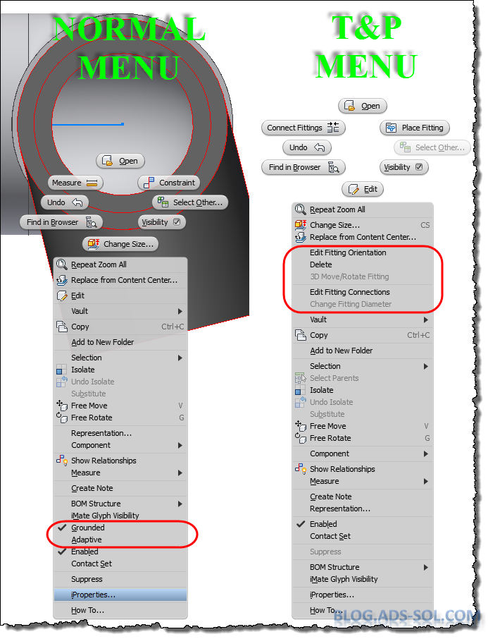
Once you publish
this to Content Center you have access to Change Size command but most
important the Insert Fitting command.
 |
| Insert Fitting is working for CC items. |
Keep in mind
that adding all these bodies will increase the size of the file a lot and for
simple parts you are better off to model it rather than adding them as
suppressed bodies which can be a bit of overkill.
Hope you are
still with me; I will do a video for this might seem too much to some of you.
For your
convenience I have attached the files in a zip document so grab
it here and start playing with it.
 |
| How do you like my next car? |
Later,
ADS.
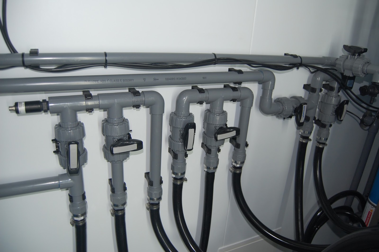
photo credit:
stay dumb! glue pinella
&
DSCF2330 (license)


