No time
for a regular post or a video but I’ve got a small ilogic code to share on
how to create and edit custom tables on drawings.
I am doing
half a dozen tanks a week and each need to have a couple of tables with nozzle
connection and tank specifications.
The tank
is done as ilogic component that I clone along with the drawing each time a new
one is needed.
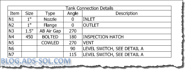
The nozzle
connection table looks like this:
And the
Operating Conditions table:
All
the info comes from the model and if they are not present then we prompt the
user for the values to fill in.
It
is better if you place and position the table before running the code otherwise
it will show up somewhere in the lower left corner, (you can always move it of
course). If you do place the table first even if it doesn't have the correct
info the code will find it and will edit it.
I
am using table name as my search criteria when going through all the custom
tables on the drawing. The limitation
would be having two custom tables with same name because it stops at the first
one so, although obvious, make sure you have different names for each of
your table; can’t call them all “table”.
TableCheck:
'------------------------------------------------------
'---------------start
finding the table----------------
'------------------------------------------------------
For i = 1
To oSheet.CustomTables.Count
TableTitle = oSheet.CustomTables.Item(i).Title
If TableTitle = "Operating
Conditions" Then
'Remember the table number for editing
section
TableNr = i
'If table found jump to
edit section
Goto EditTable
End If
Next
'------------------------------------------------------
'---------------end
finding the table----------------
'------------------------------------------------------
If the table is
not found then we are creating it and then we run the TableCheck again in order
to find the table number to edit.
'CreateTable:
'------------------------------------------------------
'---------------start
creating the table---------------
'------------------------------------------------------
' Set the column
titles
oTitles = New String(){"Item", "Description"}
'
'
'
' Create the
custom table
oCustomTable = oSheet.CustomTables.Add("Operating
Conditions", ThisApplication.TransientGeometry.CreatePoint2d(15, 15), _
2, 11,
oTitles,oContents, oColumnWidths)
'------------------------------------------------------
'---------------finish
creating the table---------------
'------------------------------------------------------
'edit the table
by restarting the check routine
Goto TableCheck
This is where we
edit the table, and we check if the model has the info we need and if not then
we prompt the user for that. When we prompt we show the user the current value
but allow him to change it if he wants:
EditTable:
'------------------------------------------------------
'---------------start
editing the table---------------
'------------------------------------------------------
'Get the name Of
the first model in the drawing
modelName = IO.Path.GetFileName(ThisDrawing.ModelDocument.FullFileName)
'MessageBox.Show(modelName,
"ilogic")
'
'
'
'
'------------------------------------------------------
'---------------finish
editing the table---------------
'------------------------------------------------------
It’s pretty much
the same for the Tank Connection Details so I won’t post that but the code for this one is
down bellow for all those search engines and linked here for you to download.
Later,
ADS.
' Set a reference to the drawing document.
' This assumes a drawing document is active.
Dim oDrawDoc As DrawingDocument
oDrawDoc = ThisApplication.ActiveDocument
' Set a reference to the active sheet.
Dim oSheet As Sheet
oSheet = oDrawDoc.ActiveSheet
'Declare my custom table
Dim oCustomTable As CustomTable
TableCheck:
'------------------------------------------------------
'---------------start finding the
table----------------
'------------------------------------------------------
For i = 1 To oSheet.CustomTables.Count
TableTitle = oSheet.CustomTables.Item(i).Title
If TableTitle = "Operating
Conditions" Then
TableNr = i
'If table found jumpt to edit section
Goto EditTable
End If
Next
'if not found go create it
Goto CreateTable
'------------------------------------------------------
'---------------end finding the
table----------------
'------------------------------------------------------
CreateTable:
'------------------------------------------------------
'---------------start creating the
table---------------
'------------------------------------------------------
' Set the column titles
oTitles = New String(){"Item", "Description"}
' You can ask user for the name of the columns if
you want
'Dim oTitles(1 To 2) As String
'oTitles(1) = "Item"
'oTitles(2) = InputBox("What to prompt",
"iLogic", "Default value")
' Set the contents of the custom table (contents
are set row-wise)
'more than one way to skin a cat
'Dim oContents(1 To 22) As String
oContents = New String(0 To 21){}
oContents(0) = "Contents"
oContents(1) = "" 'oMedia
oContents(2) = "Working Capacity (EST)"
oContents(3) = "" 'oCapEST
oContents(4) = "Dry Weight"
oContents(5) = "" 'oDryWgt
oContents(6) = "Maximum Working Weight"
oContents(7) = "" 'oMaxWgt
oContents(8) = "Specific Gravity"
oContents(9) = "" 'oSpecGrav
oContents(10) = "Max. Working Temperature"
oContents(11) = "5 Degrees C"
oContents(12) = "Max.Working Pressure"
oContents(13) = "Atmospheric"
oContents(14) = "Materials of Construction"
oContents(15) = "" 'oMaterial
oContents(16) = "Location"
oContents(17) = "Plantroom"
oContents(18) = "Tolerances"
oContents(19) = ""
oContents(20) = "Angular"
oContents(21) = "+/- 0.5 Degrees"
' Set the column widths (defaults to the column
title width if not specified)
Dim oColumnWidths(0 To 1) As Double
oColumnWidths(0) = 7.5
oColumnWidths(1) = 6
' Create the custom table
oCustomTable = oSheet.CustomTables.Add("Operating
Conditions ADS", ThisApplication.TransientGeometry.CreatePoint2d(15, 15), _
2, 11,
oTitles,oContents, oColumnWidths)
'------------------------------------------------------
'---------------finish creating the
table---------------
'------------------------------------------------------
'edit the table by restarting the check routine
Goto TableCheck
EditTable:
'------------------------------------------------------
'---------------start editing the
table---------------
'------------------------------------------------------
'Get the name Of the first model in the drawing
modelName = IO.Path.GetFileName(ThisDrawing.ModelDocument.FullFileName)
'MessageBox.Show(modelName, "ilogic")
'declare the table to edit by the number found in
check
oCustomTable = oSheet.CustomTables.Item(TableNr)
'Type of Media
Dim oMedia As String
'set the cell to edit, you can add numbers or name
'first cell to edit
oCell1= oCustomTable.Rows.Item(1).Item("Description")
'try and get it from the model
Try
oMedia = Parameter(modelName, "MediaType")
'if not found, prompt user for it
Catch
oMedia = InputBox("Contents", "iLogic", oCell1.Value)
End Try
'add media to table
oCell1.Value = oMedia
'Capacity
Dim oCapEst As String
'second cell we're editing
oCell2= oCustomTable.Rows.Item(2).Item("Description")
'try and get it from the model
Try
oCapEst = Parameter(modelName, "CapEst") & " Litres"
'if not found, prompt user for it
Catch
oCapEST = InputBox("Working
Capcity (EST)", "iLogic", oCell2.Value)
End Try
'add Capacity to table
oCell2.Value = oCapEST
'Dry Weight
Dim oDryWgt As String
'3rd cell we're editing
oCell3 = oCustomTable.Rows.Item(3).Item("Description")
'try and get it from the model
Try
oDryWgt = Parameter(modelName, "DryWgt") & " Kg"
'if not found, prompt user for it
Catch
oDryWgt = InputBox("Dry
Weight", "iLogic", oCell3.Value)
End Try
'add Weight to table
oCell3.Value = oDryWgt
'Total Weight
Dim oMaxWgt As String
'4th cell we're editing
oCell4= oCustomTable.Rows.Item(4).Item("Description")
'try and get it from the model
Try
oMaxWgt = Parameter(modelName, "MaxWgt") & " Kg"
'if not found, prompt user for it
Catch
oMaxWgt = InputBox("Max
Working Weight", "iLogic", oCell4.Value)
End Try
'add total weight to table
oCell4.Value = oMaxWgt
'Specific Gravity of Media
Dim oSpecGrav As String
'5th cell to edit
oCell5= oCustomTable.Rows.Item(5).Item("Description")
'try and get it from the model
Try
oSpecGrav = Parameter(modelName, "SpecGrav")
'if not found, prompt user for it
Catch
oSpecGrav = InputBox("Specific
Gravity", "iLogic", oCell5.Value)
End Try
'add Specific Gravity to table
oCell5.Value = oSpecGrav
'Material
Dim oMaterial As String
'6th cell to edit
oCell6= oCustomTable.Rows.Item(8).Item("Description")
'try and get it from the model
Try
oMaterial = Parameter(modelName, "MaterialType")
'if not found, prompt user for it
Catch
oMaterial = InputBox("Material", "iLogic", oCell6.Value)
End Try
'add material to table
oCell6.Value = oMaterial
'------------------------------------------------------
'---------------finish editing the
table---------------
'------------------------------------------------------
EndRule: