Showing posts with label update. Show all posts

Monday, 7 March 2016

Removing phantom fittings

                Although similar with last post I need to share some tips on how to populate a corrupted route again. Last post we discussed how to delete fittings and today we are using the info there to remove fittings and segments that don’t update. 


                This is a scenario that I see a lot and it refers to broken links and updates on the fittings. You modify a route and when you try and update the run you realize that some / all fittings don’t update position and sometimes Inventor creates a complete new set of pipes and fittings ignoring the existing ones.

                I don’t have a case at hand but I will share the one on Autodesk Forum I have been answering and which can be seen here.


                As you can see from the images, Inventor decided to keep some segments in place when the route has been changed.

                A different case would be when you need to remove the populated fittings and segments from a route like in this post here.
               
                Just like in my previous post you need to move the fittings and segments outside T&P assembly (promote) and then demote them to a new assembly which can then be deleted.

                The problem is, once you move those fittings you can’t populate the route again. We are technically hiding the elements outside TP and then we delete them so the route has no clue that the parts have been deleted.

                If you do need to populate it again then I have a trick and this is the reason we are here today.

                The route can’t be populated again but you can copy/paste it and then make it adaptive and this will replicate your exact route. Because you are doing this at the route level (instead of run level) you will get the default fittings and not any manually placed ones (valves, reducers, etc.) but nonetheless it is far better than sketching the route again.

                Inventor will NOT place the route in the original location and you will see it at a distance adjacent to the corrupted one.  As a rule any new files will be created at assembly origin and that means that any route will be located at the run origin but without constraints. You can always check the position of the original one by checking the iproperties/occurrences tab.

                You have two options to move the route to a new location:

1                1 - You have not used the Make Adaptive command yet. Once you paste the route you can then right click on it and in the iproperties / Occurrences tab you can enter 0 in the “Current Offset from Parent Assembly Origin” and then click apply. Then you can use the Make Adaptive command.

Position route at origin.
Make Adaptive menu.

                2 - If you have use the Make Adaptive and even used the Populate Route command you can repeat the steps before but in the Occurrences tab take of Adaptive first and then put 0 in the offset value fields. As soon as you click apply, the Adaptive box should be ticked automatically for you if not make sure to put it back. You can't just change the position of an adaptive route or you will get this error:
"
                "Properties: problems encountered while executing this command
                Invalid input for Request"


Take off Adaptivity first.

Limitations:

-          You still need to connect the route to your equipment around.
-          Sometimes, if the location of fittings and segments don’t update you need to edit the route and simply click on “Finish Route” to force an update. Update button or rebuild all will not help you.

Force update the fittings and segments.
Small animation of the process.

This trick is part of the “How to constrain my TP assembly and its components” blog which will come at a later time. Way too many to handle at once.

Latter,
ADS.


photo credit: fittings (license)

Tuesday, 23 February 2016

Revision Table

In this post I will share what is the best method to increase the revision number on the drawing. While this can be done in several ways there are a couple of things to consider, like choosing the scope of the revision and the revision table type (single/multiple entries).


First let’s identify the different types of revisions. When you place a revision table on a drawing you will be asked if the scope of the table will be Entire Drawing or Active Sheet.

Revision Scope
If you choose Entire Drawing then all sheets will have same revision number linked to the drawing iproperties.

TIP: In the Revision Table placing window make sure that “Update Property on Revision Number Edit” is ticked.

Choosing Active Sheet will mean that each sheet will have individual revision number controlled from the sheet properties.

Sheet Revision
You might ask yourself why would one need to control revision for each sheet? It’s all to do with internal specification, document controlling and validation. Some clients have one drawing number for all sheets and some have a separate drawing number for each sheet. Think of them as separate documents each with its own part number and revision/issue number. In some industries each document needs to be tracked, linked and controlled.

TIP: Remember to change your titleblock to indicate sheet revision rather than drawing revision.

 
Titleblock Revision info
Multiple entries Revision Table:

If the company standard is to show all or predefined number of entries in the revision table (like showing last 5 changes) then know this:

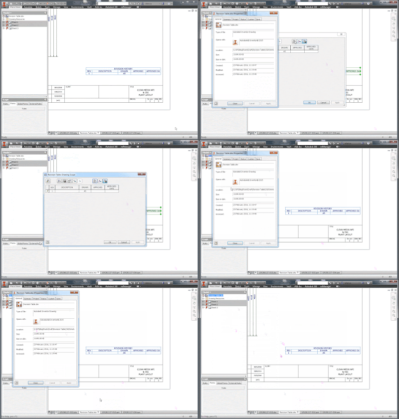
                The correct way to change revision is by choosing Add Revision Row on the contextual menu when you right click the revision table but you can also do this while editing the revision table. This will update revision on the sheet or iproperties as well which in fact will update the titleblock.

Correct way to add revision
                Do not choose add row because that will not update drawing/sheet properties or the title block. The number/letter you add with the add row will not be considered as a revision number and next time you choose Add Revision Row the numbering will increment but it will ignore your manually added row value.

                Do not change iproperties manually because, even though it will update title block, this will mess up the revision table. Changing the revision number in iproperties will not increase by adding new row and it’s same as if you edit the table and change the number manually.

Single entry Revision table:

If you company standard is to show only the current row in the revision table then changing iproperties might be your preferred choice. Entering a value in iproperties will override the last row in the table and will update the title block.

TIP: Remember that you can open iproperties from the revision table but even faster you can bring them up by right clicking the drawing name in the tabs or in the browser like this:
               
Getting the iProperties window.

                Either way you choose to use this I hope I gave you some good info to speed up your workflow.

Later,
ADS


photo credit: Woolpit Steam (license)

Friday, 20 November 2015

Defer Tube and Pipe Updates

I can understand why some of you might find this post boring and hard to read so I have sprinkled it with images from London Underground, mainly Tube Line Service Update and to be honest the first one matches my feeling and situation exactly.

My feeling exactly when Inventor T&P failed to update
                Being self taught is good and bad, and while I find solutions to my problems faster I do tend to be a know-it-all type of jerk that doesn’t take other people’s ideas and remarks easily.

                But what good is all this knowledge and skill if I don’t share the findings? On this premises today I will share a problem I had the other day and the solution I found for fixing this.

                On one of my large plant layouts I had to activate “Defer all Tube & Pipe Updates” so I can do changes to the equipment, foundation and the rest of the plant. Changing a single constraint can take forever on large assemblies especially if that implies updates to tube and pipe. On this particular job I had about 24 runs with multiple routes and even on decent CAD Workstation it can seem forever.

                So I’ve disabled updates on Tue and Pipe and I have started churning away on all the changes imposed by the client. Couple of days later when I finished I have decided it’s time to update some of the pipe routes. I usually work my way one route at a time, fixing connections, dimensions, and adding/removing elements. When I am happy with the results I turn to the next one but before I could even start I have hit a brick wall and couldn’t pass over it.


                I can’t seem to be able to turn off “Defer all Tube & Pipe Updates”. I right click the TP assembly node and choose “Tube & Pipe Settings”, tick off the option, click OK and ... nothing happens. No change of icons, they still are red lightning bolt, and the “Defer all Tube & Pipe Updates” is still marked on the T&P. First thought was to make a new TP asm and recreate the structure of all the Runs which will take a while because they are only 24 if you recall so I wasn’t really keen to do that.

It's like the Matrix deja-vu; keep ticking off and it's not working.


                First thing I tried was to open the T&P asm on a separate window and suppress all the runs, and for that I had to create a new Level Of Detail (LOD). Switched back to my original assembly and tried to change T&P representation to my new LOD and nothing happen. Stuck again I have decided to suppress the Runs from the main assembly, and now turning off “Defer all Tube & Pipe Updates” was working. Feeling that I am getting closer I tried to unsuppressed the RUNS and while they showed up they still had the red lightning bolt icon on them meaning that they might not update and cause problems down the road. I bet this is not just a glitch on the icon and I will have update problems in the future.

LOD not working either.

                I have turned back defer updates and suppressed the runs, then I started to un-supress them one at a time and to turn back on defer updates afterwards so I can track if there’s a specific run or set of runs that cause the problem.
                And I was right! One particular run once unsuppressed it didn’t allowed me to change T&P defer update settings. Using the same procedure I have narrow it down to a single route that was being my pain. Even though the route is displayed in red in the browser, which usually means there are some issues with it (not violations), I can’t seem to find what’s wrong with it. It is simple enough to be bulletproof; 8 lines fully constrained, and yet it’s acting weird.
Source of my problem.
Can't see what's wrong with it.
                Hope you never get the headache I have from T&P and hope you learned something new to try before starting over from scratch. A different solution might be to recreate the Tube and Pipe assembly altogether; just the T&P assembly though, not the routes and all that work, but I will be talking about that on a separate post.

Will end with Quote of the Day:


            Later,
ADS


Thursday, 3 July 2014

iLogic Rules

I have just spent the last couple of days playing with iLogic. I am doing a tank template that I will present in the next couple of posts and it's all been done with iLogic and iFeatures.
Meanwhile I decided to present you a couple of iLogic routines and programs I am using. I have collected a couple and hope you will find them useful.
I don't have any programming experience, so all codes have been downloaded off the internet, tried and tested.
The main ones that I use are Export to PDF, DWF, and DXF. The reason I use ilogic is to automatically add revision to the filename. You can also chose export folder so one more thing out of the way.
I also use iLogic to force update iProperties of the drawing from the model. I have a code to set the scale of the model in the drawing and one to add virtual parts to the assembly from a text document. (Curtis Waguespack's code). He also gives a code to force turning all features off down level on all components (huge time saver)
Create a folder for your iLogic codes, recommend to use a map network drive location so they are available for all users in your company.
Open a file and go to Manage \ iLogic \ iLogic Browser , switch to External Rules tab. Right click and add external rule. Add your rules, in my case UpdateProps (force update of properties), SavePDF, SaveDXF, SaveDWF.


Switch to Global Forms and Add Form. If you have a common Design Data folder on the network then this Form will be available to all users ;) . Drag your rules on the right and change the name of the buttons and of the form if needed.


I know you can add buttons on the ribbon and quick access bar but you need to configure it with every new Inventor release so I prefer to have a global form instead.
At times I need to do a batch of files so I use Code Injector, a small utility that will do that for you. We once had around 900 drawings to export to dxf and pdf so we just left the injector run overnight. Here is the post and description. http://beinginventive.typepad.com/being-inventive/2012/02/injecting-ilogic-code-and-ilogic-event-triggers-automatically.html


Virtual Components
Issue:
You have a number of standard Virtual parts that you find yourself adding over and over. You'd like to have the ability to add them based on a predefined list.
Check his blog here for the code.
I use this to add various stuff like: oil for gearboxes and hydraulic units, paint and primer, chemical for anchor bolts, grout, etc.

Work Features
Issue:
You have other members of your design team that do not remember to turn off work features at the part level or sub-assembly level when they are done working with those files. As a result file previews and view representations get messed up. You'd like to have a quick way to toggle all of the work features off. Can this be done with iLogic?
 Check his blog here for the code.

Update copied properties.
Issue:
You have a lot of drawings that need update copied iproperties of the model (updates copied iproperties of the model in the drawing).
Solution:
Use the code to force the drawing to update copied properties from the model. Can be used with Code Injector to do a batch of drawings at a time.
File to be used: UpdateProps.iLogicVb

Save PDF
Issue:
You have to export one or many drawings at a time to pdf.
Solution:
Use the code to export current drawing to pdf. It creates (if didn't exist) a folder called DXF on same path as drawing (needs saving first) in which a pdfwith the filename being "Drawing_filename + Drawing_description + Revision". Can be used with Code Injector to do a batch of drawings at a time.
Make SURE that the drawing is saved otherwise the path of the folder and pdf will be on root drive.

Save DXF

Issue:
You have to export one or many drawings at a time to dxf.
Solution:
Use the code to export current drawing to dxf. It creates (if didn't exist) a folder called DXF on same path as drawing (needs saving first) in which a dxf with the filename being "Drawing_filename + Drawing_description + Revision". Can be used with Code Injector to do a batch of drawings at a time.
Make SURE that the drawing is saved otherwise the path of the folder and dxf will be on root drive.


Scale of first view in titleblock

In order to have the scale show up and update automatically in the titleblock, do the following.
Edit your title block definition and add a Text item with the type Prompted Entry
This text should contain <Scale>

After you add this, Inventor will prompt you for a Scale value whenever you add the title block to a sheet.
The same happens when you add a new sheet with the title block to the drawing or when you start a new drawing using a template where you have applied this solution.
When it prompts you, just leave the value blank

Then add the rule in text bellow to the drawing
File to be used: Prompted_Scale.txt
Add the rule to the trigger “Before Save Document”

After that, on every sheet in the drawing, you will get the scale value from the first view on that sheet in the title block when you save the file.


What rules do you use? Please let me kow what's your favorite?
ADS