Showing posts with label symbol. Show all posts

Monday, 16 November 2015

Placing Symbols

Old habits die hard and it’s a constant fight to change them. For all my life when I place a note or symbol I right click and choose continue while I could double click to finish placement.


Start the Leader Note, Insert Symbol, or any other item on the Symbol panel of the Annotate tab, click on the element to detail then move the mouse out and then double click to place it.


I’ve mentioned before that I left the engineering office for about 4 years and changed to inspecting and installing equipment and starting up a couple of plants and while that was really rewarding and helped improved my knowledge I have fallen behind on all things CAD. When I came back to Inventor, Autocad and designing in general I was struggling to find the commands and the menus again but my mind had a mind of its own. After a week or so I found that my hand knew the shortcuts and started commands before I could tell what was going on and before I could realize what the shortcut for that command was. This goes to prove how hard it is to change my habits especially if in a hurry and I switch to auto-pilot letting my mind’s mind work out the details of what to click, where and for how many times.

To further help this habit installed if I find myself placing a note or symbol by using the Right-Click Continue option, which is an automatism by now, I delete it and recreate it with double click. I feel that doing the extra work of recreating the steps to be annoying enough to force my brain to switch tactics and update the habit.

Of course, unlike the right-click continue option which can be used all the time without exception, the double click is tricky and need special consideration in things like Surface Texture where you need to move the mouse out to specify the direction of the symbol and then come back and double click on the original point.

I don’t think this alone will improve speed and get your drawings out faster but changing a lot of these small things can have a good impact so try them out.

Later,
ADS


photo credit: Continue via photopin (license)

Friday, 23 October 2015

Text Mask


            This will continue exploring our drawing symbols and notes in Autodesk Inventor. Last post we discussed how to hide the leader but maintain attachment link and position.
            If you use AutoCAD a lot you might wonder if there is a way to create text masks in Inventor. Sadly there isn’t but there are other ways to hide objects behind your symbol or note.

            Out of the box but turned off we have the Cross Hatch Clipping option that will trim the hatches with a box around your texts, like on dimensions, notes, or symbols.
            To turn this on, which I do because it looks better and makes the text legible, you need to open Document Settings on the Tools tab, Options panel of the drawing. In the document settings window head over to the Drawing tab and tick the box on Cross Hatch Clipping.


            Once that is on and you have text overlapping hatched areas you should see the hatch being trimmed by a rectangular box around your text.
            On the left Cross Hatch Clipping is off and on the right is on. It does look better doesn’t it?


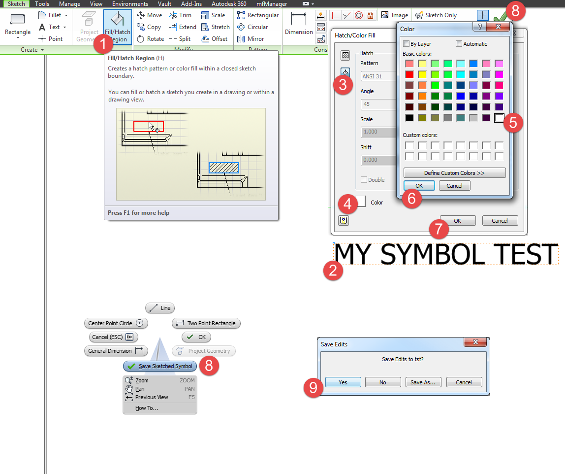
            Just like in Autocad I want/need to create mask on text and it’s not possible out of the box in the edit text dialog window but that’s where we become creative. You need to turn your text into a symbol because that will put you in the sketch environment where we can use the hatch/fill to put a solid color behind our objects and so in the drawing they will hide objects behind them just like a mask in Autocad.
            TIP: You need to create them a symbols and not by activating sketch or draft view because you can attach it with a hidden leader and they can more easily be copied around on other sheets or drawings.
            On the drawing browser right click the Sketched Symbols folder in the Drawing Resources node and choose Define New Symbol. Then create your text but make sure you turn the Text Box option on.


            At this point the text dotted line cannot be used for filling/hatching but you can either draw a rectangle on top of the text border or what I like to do is use the offset command and put another border around my text. On the Sketch tab choose Fill/Hatch Region and click select your profile, and then select Color Fill option and click the Color button on the bottom. Choose your color, click OK to exit the fill/hatch dialog and then save your symbol.


            This method is not perfect and there’s missing functionality here but once you used the fill command to put a mask in the symbol you can also edit the Symbol (not Edit Definition) and choose Symbol Clipping. This will remove extension lines behind the symbol like from dimensions and other leader texts.
On the left you have Symbol Clipping on and in the right of.


            Although it’s slightly better, still not perfect because centerlines and other cosmetic entities (drawing items) will show on top. We do need a Send to Back, Bring to Front, Bring on Top and Text Mask like in Autocad. I would still check the export to dxf and pdf to see what the results are in terms of top layer priority.


 Give it a try and let me know how that goes.

Unfortunately in 2016 the fill/hatch will not hide objects behind it but we are waiting for the fixes.


Later,
ADS

photo credit: Star Wars Weekends 2011-Last Day via photopin (license)

Wednesday, 21 October 2015

Floating Symbols


I quite like the new symbol library and the fact that it supports dwg files as well.  It’s something I need to test and to be honest we still use idw as the default drawing format just because the file size is smaller, because Inventor will create the data as a block in dwg and mostly because of habit and resistance to change. But that’s not what I want to discuss today.


I want to show you a magic trick on how to have notes and symbols linked and moving with a view even though they appear to be floating around it.

            In most of the cases the symbols will have a leader and an attachment pointing and sometimes I need to drop them on screen as part of the view but without being attached to a specific element. A note like the sheet metal details we have been discussing here, which I like to include before exporting my drawing to dxf and sending it over for laser cut. That note needs to be on the drawing but I like to attach it to the view so that if I move or copy the view it moves the symbol as well.

            The way to create floating notes glued to the view is to use symbol notes and the trick is to take off leader visibility. This way the symbol is attached to the view and it just looks like it’s floating around.

Floating Symbols

            This is also good for general notes if you don’t have a separate demarcated area on your drawing or you need it next to the view. When the drawing grows with added dimensions, notes and callouts and you need to move it, the general notes symbol will move and maintain its position in regards to the view.
            Start the symbol with the shortcut (mine is set to "sy") or from the Annotate tab, Symbols panel or by right click it on the Drawing Resources, Sketched Symbols folder and choosing Insert.


            You can double click the symbol and choose an attachment point but there's a catch. If you do it this way the leader visibility cannot be turned off until you drag the symbol from the default place location. Then the the extra options Leader and Visibility are available.


            In conclusion, if you move or copy views you might want to do you notes as symbols (still a leader note) but you can control the visibility of the leader and the attachment point and if you move the view around the note goes with it. And furthermore you can have it in the template.idw symbols ready to drop in.


Later,
ADS

Photo credit: Crowned via photopin (license)