Monday, 26 December 2016

Previous versions of software

Did you know you are entitled to get previous versions of software from Autodesk?
               
All the versions I need

                It’s a long shoot and most of us can’t want to jump on the latest and greatest so who would need to bloat up his drive with unneeded stuff?

                You all probably keep the old version around for 6 months after rolling up the new one but why would I install a previous version on purpose?

                My spare time job as help desk support engineer requires me to have all the version I can have really but would you?

                Just the other day I ran into this case where importing forerign cad data was not possible in 2017.3. It worked with one model at a time and it would popup the AnyCAD functionality rather than the good old translate import.

                I thought I could outsmart it and use the task scheduler but that failed to work and I keep getting errors no matter of the import procedure, reference vs conversion to inventor iam,ipt.

                That’s when previous version came in hand and I was able to use task scheduler from 2015 to automate the translation.

                It was only a small step to migrate them all to latest version with task scheduler of 2017.

                While I hope you never get the need to use a previous version here’s the info Autodesk has on the knowledge center.

                You can only access a version you had a license for and the number of copies must match whatever you had at the time when that previous version was current.

                It’s a bit more complicated really but that’s the general gist of it.

                In order to get a previous version license you need to login in to accounts.autodesk.com, or ask your account administrator to do it for you, expand the product you need and use the “Get Serial Number” link on that product. More info here

                Later,
                ADS,


photo credit: CGP Grey Lord of the Dice (license)

Friday, 23 December 2016

Fitting Alignment Issue

What’s wrong with these fittings?
 
Weird alignment

weird again.


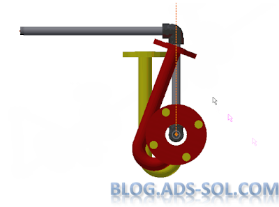
My fitting orientation is all wrong.  You will get this especially on zero dead leg valves for pharmaceutical products but I’ve seen this on other products.

If you create a plane between the 3 connection points of the valve you will see that it’s not parallel with the rest of the geometry, valve body in my case.

default orientation

The direction is given by the 3’rd connection perpendicular to the line between the first and second. I think this is to help out with inexperienced users, idiot proof really, helping out if you didn’t align your connections to the model but that's just for straight fittings like tees.

Now what? Am I supposed to measure the angle every time and change fitting orientation on a continuous loop? (rolling eyes).

In order to fix this you need to add another authoring point and make it a 4 point connection.

4 Connections on a 3 point fitting? Are you mad?

I thought we already established that and we’re here to have some fun and solve some problems.

 We will be creating the 3rd connection inline (same plane) and parallel with the fitting as spare, never to be used and instead the 4th connection is to be used.

It might help to make the 3rd on a different plane away from 4th like right on the origin line just so it’s out of the way when placing or connecting fittings to it. We want to make it very obvious from the snap preview that it’s not the one to be used.

authoring dialog window

I have also gave it a really small connection size; a size we would never use like 1/8” to differentiate it even more and keep people from connecting to it.

And this is what the difference between placing a 3 or 4 connection fitting looks like
 
compare the results.
I’ve given this example before on autodesk forum on a similar issue.

You can keep just 3 connections if you align the third but we can do better.

3 would do but 4 is better


I feel it’s best to have a 4’th connection but be careful on placing fittings.

Watch out for ghost connection when placing this fitting. 

Later,
ADS


Wednesday, 21 December 2016

Punch iFeatures

You have no excuse!


iLondon
I will explain this one again and you will no longer have an excuse.

 You will have to force yourself and use it but trust me it will save a lot of time and increase your productivity.

I’ve seen this one too many and it’s killing your productivity and possibly your enthusiasm on using features, especially punch features.

First of all what are iFeatures?

Autodesk dictionary helps us out:
“Converts a single feature or a collection of features into a feature you can reuse in other part files.”

The definition is a bit circular, I agree. What that means is that if you model the same things everyday (keyways, for example) then you better make those an iFeature and reuse them.

Furthermore the iFeatures can have a table and you can generate custom sizes from easy to use forms with drop down menus and you can even have custom prompted values, with range and increment.

You will get a new file type "ide" but you can even drag-drop it from windows explorer.

I use them all the time and I have all sorts of ifeatures like flanges, ferrules, pipes, but especially features for my tanks and vessels, like manholes-manways, spray balls, feet, ladder attachments, lifting trunions, on and on...

One essential rule is to have the feature self-contained and do not reference any other geometry. If you do need to make it depended then only reference features to be included in the ifeature element.

 A special case are the Punch iFeatures for which the first element needs to be a sketch with a work point; this will be used as the insertion point and is especially helpful with recurring patterns.

We are here because you spent a lot of hours planning ahead, tested your ifeatures and perfecting the technique of making them independent and yet they fail to work. The work feature is not normal to the face and you have punches that are not protruding the sheet metal part.

And that is because your work is too perfect! That’s right, you need to take a step back, don’t make it quite that independent and reference the sheet face.

Typical procedure is to create a sketch and place a work point on it. Then create a construction line trough the point and finish the sketch.

Now you have the insertion point for your punch ifeature. You then create a work plane where you model the sketch of the punch.

The wrong way to do it is to create the workplane from the sketch workpoint and the sketch construction axis. At this point the ifeature will have no reference to the sheet face and it will spin in space as it sees fit.

Wrong way of doing it:


Wrong way of doing it

Correct way of doing it by referencing the construction line and the face where the sketch is defined.

Correct way of doing it

Don’t worry the face has been referenced before when you created the insertion point so you'll still have only one reference to pick when placing this.

Wrong way of doing it, end result:

Wrong way - wrong results

Correct way of doing it, end result:


Correct way - correct results

Repeat after me:
“I will use ifeatures from now on, save time and increase productivity”

 Later,
ADS


photo credit: @Doug88888 London - Light painting London (license)

Component Sketches Off


I hate when people don’t clean up their models. Although not right my mind associates this to a messy person with unclean desk, car, and garage, buried in piles of unneeded stuff.


                OCD is my middle name and while I hate this side of you, I love you as well and I think maybe you weren’t taught how to do it properly.

                I suggest you never use the “Object Visibility” drop down on the View tab.

I NEVER USE IT; except to see if you’ve been cheeky and got this quick fix like a drug addict.

It’s a crapshoot and it will bite you faster than you think. Have you considered the time, effort and stress you are going to experience when using this in large assemblies.

That’s all I am going to say and I will share  a bit of iLogic code I use to clean up this mess I see regularly with sketches not being turned off.

I have another one where I turn off the visibility of workfeatures, WorkPoints, WorkAxis, WorkPlanes and I like to keep it separate from the sketch visibility because when using it with tube and pipe it will turn the routes off and I don’t want that.

Component Sketches Off

I have also wrapped the whole process as a single transaction because if I need to undo the operation I only need to do a single undo not clicking back for each sketch that is off.


Code below and in this download link

-------------------------------------------
'catch and skip errors
On Error Resume Next
'define the active assembly
Dim oAssyDoc As AssemblyDocument
oAssyDoc = ThisApplication.ActiveDocument 

'get user input as True or False
wfBoolean = InputRadioBox("Turn all Sketches On/Off", "On", "Off", False, "iLogic")

' Process the rule, wrapping it in a transaction so the 
' entire process can be undone with a single undo operation. 
Dim trans As Transaction 
trans = ThisApplication.TransactionManager.StartTransaction( _ 
        oAssyDoc, "Sketches Off")

'Check all referenced docs
Dim oDoc As Inventor.Document
For Each oDoc In oAssyDoc.AllReferencedDocuments
    'set Sketch visibility
    For Each oSketch In oDoc.ComponentDefinition.Sketches
    oSketch.Visible = wfBoolean
    Next    
    
Next

'end transaction for single undo
trans.End 

'upate the files
InventorVb.DocumentUpdate()
-------------------------------------------


Later,
ADS
photo credit: Rubina V. Jahrmarkt (license)

Monday, 19 December 2016

Phantom Branch Fitting

I must have lost it! Right?


                Who, why and where would one use this? A lot of you will use this.

                This blog is part of a series on creating branch take offs with pipe cut-backs and as you have probably quested we will create pipe side holes with branch fittings.

                Another one of my internet friends has asked about this long ago and it stuck to the back of my mind until the answer came on a sleepless night. He is doing a lot of irrigation projects in Africa and parts of the world where labor is cheap but materials are expensive and so they NEVER use tees, but rather drill the main pipe and weld a branch pipe straight on it.

                I recommend that you create empty fittings, but it could be useful to add some geometry like surfaces or work features to better locate it in the graphical window.

                What good is an invisible part when you need to select it and edit it, change size, rotation, engagement, the whole lot.

                While I documented how to create branch fittings with a single connection point (pipe clamps) I think you need and will end up using both connections.

                I have taken a normal pipe from content center and stripped it down of all the features, then I have made it an ipart and finished by copying the relevant pipe sizes from the original content center family table into my ipart.

                You don’t need to remember all this, I intend to create a video as well and I will provide the files at the end as usual.

                As this will only serve o create our pipe cutout we need to set the BOM status to Phantom and you can do that straight from the iPart by opening Tools, Document Settings, BOM tab. While you can do that from the assembly you would be better off to create it as Phantom from the start, I can’t imagine a single scenario where you would want this in the assembly as anything else than Phantom…… wait… spoken too soon.


Add caption


You can probably assign a cost, time, resources … to this file if you calculate cost from the BOM. So it will be just like a virtual part containing the cost, time, resources etc. for creating the drill in the pipe, creating the notch on the branch and welding altogether. I doubt you will do this, but ... you might model the welds in here and have them as a separate model ! will detail this later on.

I will use the ASME BPE pipe because I have that at hand as an iPart. I know you usually use pulled tees for this but this is a special case, not here to create pulled tees, that’s a different blog ;)

We will once again create some work points and work axis to help us author an empty part.

I would create a Min Max pipe size as separate rows in the ipart to use in the authoring info. Min is the actual pipe size and max is the max you have for that family. A 3/4" will have a min of 3/4" and max of 6” (in my case) but set this as you see fit.

Don’t forget to add a cutting sketch and mark the Cut Pipe option in the Authoring info.


Cut Profile

On the publish to content center window, or later from the edit family dialog window you might want to select a different picture or it will publish with an empty picture and it will be hard to identify.

How do you like this one?


CC family thumbnail


When you place this it snaps to a pipe segment and it creates the hole in the pipe without showing any model geometry and without showing up in BOM and Parts Lists.

However now it's really easy to start and connect a new route as it snaps to the authored point in the branch fitting.


Branch Cut-Off

The only limitation I see is you can’t create more than one branch in same spot, like if you need more than one side drills for take offs, or...... can you?

Brain is ticking …. Might have something, stay tuned.

Later,

ADS

Friday, 16 December 2016

Default Model Orientation

Wish you could change Inventor default Z orientation?


You’re not the only one and I see that in general with people switching cad software or machinists used to have the Z pointing UP.

                The UCS is set in the template file, iam, ipt, ipn, but there is also a global setting in tools application options.

                Two ways you can change the default settings.

- right click on the view cube and choose Options

- click the “ViewCube” button in Tools / Application Options / Display Tab.


Application Options


ViewCube Options

On the ViewCube Options window in the Default ViewCube Orientation change Front View Plane and Top View Plane as you see best for your workflow. I assume you will choose “XY(+Z)” for Front and “XZ(+Y)” for Top but that might be different for you.

Now you can open the template files (iam, ipt, ipn) and change default orientation.


TIP: A quick way to change the template is to choose New, select your template, do the changes and the use the File / Save As / Save as Template. You will be redirected to the templates folder where you can override the template file you have opened.

Save As Template

The orientation in the template will be used when creating new files but if you use the Reset Front option on the viewcube, it changes as per the settings in the Application Options or ViewCube options.

On the view cube you can set a different orientation for front and top on the “Set Current View As” submenu but you can also use the Reset Front which will align it to the application options.

This will also affect the lights and shadows for studio and renderings so keep the page in your bookmarks for later on.

From now on when you deal with foreign models you can change orientation on the fly by resetting the view

Later,
ADS


photo credit: branestawm2002 Port William (license)

Wednesday, 14 December 2016

RAL Library 2017

                Looking for RAL library? right place to be.

RAL library

                A while back I have posted a RAL appearance library and it’s been copied, shared, and spread all over, some crediting while others not but you can still identify your own work especially if you’ve done a mistake or two.

                While I don’t use it anymore I have been asked by colleagues on my previous company to see if I can migrate, update it to work with 2015 and now with 2017 so I’ve decided to share it once again for the greater good. Some people will take credit, not doubt about it but that’s life and not why we are here.

                Unfortunately it didn’t quite migrate as expected and I am seeing the colors a lot brighter in 2017 preview window almost as if they had self illumination, which I did check and it’s not.

Don’t be fooled by this, it’s only the preview thumbnails that have brighter aspects and the models will look right, and so the edit appearance window.

Small mismatch

                Use it as it is, good or bad it’s still better than renaming an existing color manually every time.

                This is especially useful in 2017 now that we can use the appearance as a reported property, in parts lists, bom, notes, etc.

                From the what’s new pages of AIP 2017

Appearance property
The model Appearance value is added as a selectable property. You can add the Appearance property to a bill of materials, or a parts list.


Appearance property

                While I can send the library and provided a detailed description on how to attach and use it, I feel it’s better if I just give you a part with all the appearances locally and you can copy it to your preferred library.

    Don’t you think so?

Almost forgot to share the link, that would have been useless ! 


Here is the 2017 part file.

Later,
ADS

Monday, 12 December 2016

AutoCAD Electrical Tags in Inventor?

Sharing the knowledge does a whole lot of good and I find that personally very rewarding.

What!? just use post-it...

Every once in awhile, on rare special occasion that can even return back in a multiplied form and the stress, wear out, paranoia, moody states from all the sleep deprivation goes away and you feel exalted again; not too long though, I got used to a level of tiredness and stress it’s hard to work otherwise.

We talked long and detailed (maybe too long) about how to create tags and balloons for equipment on the drawing. I was talking from a tube and pipe point of view but I have mentioned that this will be good for electronic components as well.

We talked about the general concept of drawing tagging, tagging the assembly, both together and even tagging top level components rather than end of tree fittings.

This can be very useful, and Colbjørn recognized the potential so he has adapted the code to help him get AutoCAD Electrical Tags into Inventor Drawing.

But the most important part is that he has shared the code for others to use, adapt, modify.

To be honest I wish I had his programming skill but I am, as often like to call myself, just “a mouse operator”.

You can find the original code here but I have added it down below (hope he doesn’t mind) for you.


Sub Main()
    test(ThisApplication)
End Sub

 Private Sub test(ByVal app As Inventor.Application)
    Dim oDrawDoc As DrawingDocument = app.ActiveDocument
    Dim oSheet As Sheet = oDrawDoc.ActiveSheet
    Dim oBalloon As Balloon
    
    For Each oSheets In oDrawDoc.Sheets
        For Each oBalloon In oSheet.Balloons
            Dim oLeader As Leader = oBalloon.Leader
            Dim oLeaderNode As LeaderNode = oLeader.AllNodes(2)
            Dim oGeometryIntent As GeometryIntent = oLeaderNode.AttachedEntity
            Dim oDrawingCurve As DrawingCurve = oGeometryIntent.Geometry
            Dim oModelGeom As Object = oDrawingCurve.ModelGeometry
            Dim oComponentOccurrence As ComponentOccurrence = oModelGeom.ContainingOccurrence
            Dim attrbSets = oComponentOccurrence.AttributeSets
            Dim attrbSet = attrbSets.Item("com.autodesk.mechatronics")
            Dim attrib = attrbSet.Item("ComponentTag")
            Dim oBalloonValueSet As BalloonValueSet
   
            If oBalloon.Style.Name = "Tags" Then
                For Each oBalloonValueSet In oBalloon.BalloonValueSets
                    oBalloonValueSet.OverrideValue = attrib.Value
                    Exit For
                Next
            End If
        Next
    Next
End Sub


Thanks Colbjørn for sharing it; if you find it useful go give him kudos.

Later,

ADS


photo credit: Dean Hochman post-it notes (license)