Tuesday, 27 October 2015

Leader Text

I am having a déjà-vu and I bet you’re having it too. We just talked about hiding leaders on symbols, putting mask on texts and now we are discussing leader notes? What more can there be?


You all probably know about leader text and you use it already but did you know that you can have text on leader and it’s not just a play of words? If you didn’t know, keep on reading and if you did congrats because you can tick one more box on your Inventor Expert checklist.
Any element that has a leader like, balloons, texts, welding symbols, surface roughness, custom symbols, datum identifier, etc., allows you enter custom text on its leader.  This will only be available on the first part of the leader, not any of the landing segments or its vertexes.
                Once you’ve placed your symbol you can right click on the leader and on the contextual menu choose “Attach Text to Leader...”.  This will bring in the text dialog box where you can enter your text or even use part parameters or iproperties.
                Let’s look at some examples (and please don’t tell me the text doesn’t make sense; they are just examples ;).
               
Leader Text


Datum Identifier


Welding Note


Surface Roughness


Balloons


Custom Symbol


Here’s a short animation in case you are too bored to read it all.


I hope you will use this trick if you aren't already and see you all next time.


Later,

ADS

Friday, 23 October 2015

Text Mask


            This will continue exploring our drawing symbols and notes in Autodesk Inventor. Last post we discussed how to hide the leader but maintain attachment link and position.
            If you use AutoCAD a lot you might wonder if there is a way to create text masks in Inventor. Sadly there isn’t but there are other ways to hide objects behind your symbol or note.

            Out of the box but turned off we have the Cross Hatch Clipping option that will trim the hatches with a box around your texts, like on dimensions, notes, or symbols.
            To turn this on, which I do because it looks better and makes the text legible, you need to open Document Settings on the Tools tab, Options panel of the drawing. In the document settings window head over to the Drawing tab and tick the box on Cross Hatch Clipping.


            Once that is on and you have text overlapping hatched areas you should see the hatch being trimmed by a rectangular box around your text.
            On the left Cross Hatch Clipping is off and on the right is on. It does look better doesn’t it?


            Just like in Autocad I want/need to create mask on text and it’s not possible out of the box in the edit text dialog window but that’s where we become creative. You need to turn your text into a symbol because that will put you in the sketch environment where we can use the hatch/fill to put a solid color behind our objects and so in the drawing they will hide objects behind them just like a mask in Autocad.
            TIP: You need to create them a symbols and not by activating sketch or draft view because you can attach it with a hidden leader and they can more easily be copied around on other sheets or drawings.
            On the drawing browser right click the Sketched Symbols folder in the Drawing Resources node and choose Define New Symbol. Then create your text but make sure you turn the Text Box option on.


            At this point the text dotted line cannot be used for filling/hatching but you can either draw a rectangle on top of the text border or what I like to do is use the offset command and put another border around my text. On the Sketch tab choose Fill/Hatch Region and click select your profile, and then select Color Fill option and click the Color button on the bottom. Choose your color, click OK to exit the fill/hatch dialog and then save your symbol.


            This method is not perfect and there’s missing functionality here but once you used the fill command to put a mask in the symbol you can also edit the Symbol (not Edit Definition) and choose Symbol Clipping. This will remove extension lines behind the symbol like from dimensions and other leader texts.
On the left you have Symbol Clipping on and in the right of.


            Although it’s slightly better, still not perfect because centerlines and other cosmetic entities (drawing items) will show on top. We do need a Send to Back, Bring to Front, Bring on Top and Text Mask like in Autocad. I would still check the export to dxf and pdf to see what the results are in terms of top layer priority.


 Give it a try and let me know how that goes.

Unfortunately in 2016 the fill/hatch will not hide objects behind it but we are waiting for the fixes.


Later,
ADS

photo credit: Star Wars Weekends 2011-Last Day via photopin (license)

Wednesday, 21 October 2015

Floating Symbols


I quite like the new symbol library and the fact that it supports dwg files as well.  It’s something I need to test and to be honest we still use idw as the default drawing format just because the file size is smaller, because Inventor will create the data as a block in dwg and mostly because of habit and resistance to change. But that’s not what I want to discuss today.


I want to show you a magic trick on how to have notes and symbols linked and moving with a view even though they appear to be floating around it.

            In most of the cases the symbols will have a leader and an attachment pointing and sometimes I need to drop them on screen as part of the view but without being attached to a specific element. A note like the sheet metal details we have been discussing here, which I like to include before exporting my drawing to dxf and sending it over for laser cut. That note needs to be on the drawing but I like to attach it to the view so that if I move or copy the view it moves the symbol as well.

            The way to create floating notes glued to the view is to use symbol notes and the trick is to take off leader visibility. This way the symbol is attached to the view and it just looks like it’s floating around.

Floating Symbols

            This is also good for general notes if you don’t have a separate demarcated area on your drawing or you need it next to the view. When the drawing grows with added dimensions, notes and callouts and you need to move it, the general notes symbol will move and maintain its position in regards to the view.
            Start the symbol with the shortcut (mine is set to "sy") or from the Annotate tab, Symbols panel or by right click it on the Drawing Resources, Sketched Symbols folder and choosing Insert.


            You can double click the symbol and choose an attachment point but there's a catch. If you do it this way the leader visibility cannot be turned off until you drag the symbol from the default place location. Then the the extra options Leader and Visibility are available.


            In conclusion, if you move or copy views you might want to do you notes as symbols (still a leader note) but you can control the visibility of the leader and the attachment point and if you move the view around the note goes with it. And furthermore you can have it in the template.idw symbols ready to drop in.


Later,
ADS

Photo credit: Crowned via photopin (license)

Tuesday, 13 October 2015

Place Multiple Fittings

I use a lot of Georg Fischer fittings to do my plant layouts but not all have been properly dimensioned in the catalogue and because it would take too long to identify and create an ipart / content center family, I usually author and place them as individual fittings.

piping as an art?
I know that I lose the possibility to Change Size but it’s not taking long to change them with place fitting command. If I need to change size of a component I can right click, choose iproperties, copy the file path, use the place fitting command and paste the file path, double click on new size, and all this takes less than 5 seconds, almost as much as it would take to wait for the change size menu and the family table to show up.

Because the original files are provided in a neutral file format like STEP I need to open each and every, author it and save it to library and I found that it’s faster to do it from an assembly. I drag-drop the step files inside an empty assembly, then edit each in place, author it and then save the  files. I can also check them into Vault real quick this way.

Another reason for doing this in the assembly environment is to be able to set part number and description for all of them at once by copy paste from an excel file to the BOM window. You can of course change any other iProperties custom or not.

The other day I had to change description to all my ABS Socket Welded Check Valves so I started a new assembly and then used the place component command. In the select component window I have browsed to the library folder and selected all the valves but when you click OK Inventor will place just the first selected component because it’s an authored Tube and Pipe Fitting. Lazy as I am I didn’t’ wanted to kill my finger or the mouse so instead I have dragged them from windows explorer inside the assembly.


When you use the place command inside an assembly, if you have enabled the T&P add-in you will see that the parts come in as fittings (blue elbow icon on the browser). But if you drag-drop them from windows explorer they are placed as standard components. This will not affect them in any way and it's just a visual indication only.

So next time you need to edit a lot of fittings, or need to add a set to use in the assembly, remember to drag-drop them from windows explorer. Now you can edit them all at once form BOM editor or use the Place Fitting command on them rather than browse and select every time.


Later,
ADS

Wednesday, 7 October 2015

Inventor Updates

I wasn’t sure we were allowed to say anything but now we can.
Do you think Inventor 2016 is one of the best releases ever? Well things are only getting better. Every Service Pack will include new functionality not just patches and fixes. The new release will incorporate Shape Generator, Force Effect and updated functionality for Printed Circuit Board (PCB).
                Shape Generator is amazing and I can’t wait to play with it. You specify your boundary conditions and let Inventor tell you where to add or remove material to meet your design criteria.

            Shape Generator preview

            Printed Circuit video:


Force Effect has been available for a while on Android and Apple devices but it’s nice to see it working with Inventor.


Additional information on new Inventor version can be seen here.
Read the full article from In theFold blog that explains all this. Glad it's out and I can share it with you.

Later,
ADS


Friday, 2 October 2015

Delete Pattern keep Components

I have been absolutely swamped with work and problems but I am slowly getting back to speed.

Really short one today as it's more to push things going but hopefully there's good info you can pick up.

If your design changes and where originally you had pattern of components you now need regular placed components to be manipulated and moved around then here’s a little trick.

                Usually when you delete a pattern all occurrences in that pattern will get deleted and only the first instance of the components will be preserved. The trick is to create the occurrences independent first and then you can delete the pattern which in fact will preserve any components and the position they had even if they were manually moved.

                 For a plant layout I did the other day I was told that the allocated space has shrink and we are now required to fit the units as best we can changing a nice pattern into whatever works. The units to change are quite big and for that matter I had to simplify/derive them to conserve memory and improve performance.

                Along with the sales engineer we took a quick look and moved the components around by the old pick and move routine. When we were pleased with the results I have created each component independent and then I have deleted the pattern. Each component has kept its move location  except for the first item in the pattern that Inventor has dragged back to the original constrained position.

                So you can first suppress the constraints of the main component (or activate defer update) then make each component independent and only then you should delete the pattern.


Later,
ADS

Thursday, 17 September 2015

Length parameter format

Those of you working with frame generator or with content center steel shapes know that in order to get the length parameter to display correctly you need to edit the parameter formatting.

So how do we change the content center steel shape template?

Now you have two options:
The first one would be to open the file from Content Center and for that you can click on the big I top left (inventor menu) and in the open flyout menu choose Open from Content Center.
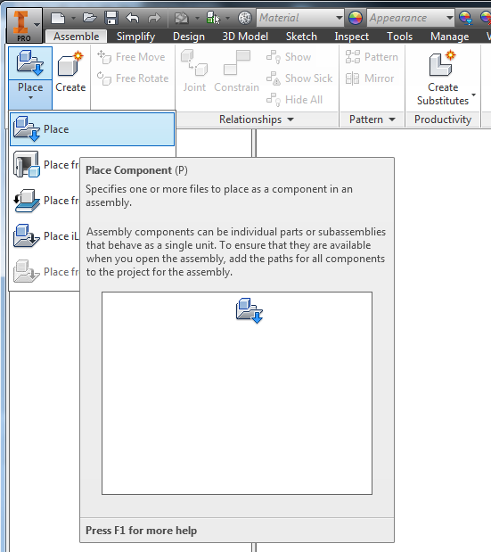
The second option is to edit an already generated file or create one by using place from content center in an assembly.
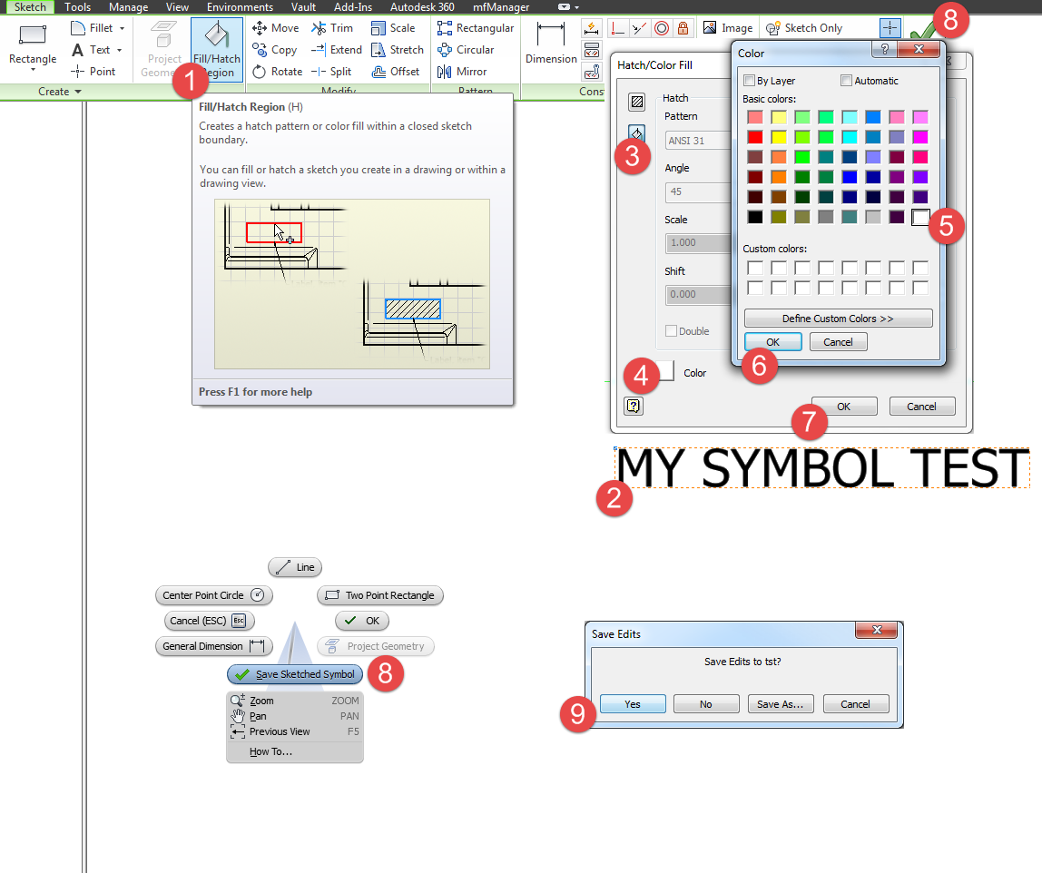
Once you have the part open you can edit and format the parameter display and then you will need to update family template in content center using this new file.

Let’s detail the first option which seems a bit quicker as well. You need to copy the family first and then generate the file because otherwise Inventor will complain that the new template is not a valid file.

- To copy the content center family to a read-write library like My Library provided by default use the Content Center Editor from the Mange tab, Content Center pane and browser to the family.

- Right click the family and copy it to your library.


- Click on big I top left and from the Open fly-out menu choose Open from Content Center, then choose the family you just copied and in the member window make sure you choose Place as Custom. Length and size it's not important so choose any.


- It will then prompt you for a save location and then will open the file for you. Now you can edit the parameters removing trailing, leading, units, and change precision to suit you.


- Now you need to edit Content Center again with the Manage button and then change from Merged View to your library (THIS IS IMPORTANT) or the extra commands will not be available.

- On the contextual right-click menu choose Replace Family Template and select the file you have edited.


So how about all those files generated already?

 Unfortunately you need to open and edit each and every file individually or use code injector and run this code.

Code injector can be found here and the original ilogic code was posted on the autodesk forum by Curtis Waguespack so head over to the original post and give him kudos.


'-------------start of ilogic code ----------------

'get the parameter
oPL = Parameter.Param("G_L")
'export the paramter as an iProperty
oPL.ExposedAsProperty = True
'set the parameter as a custom property
oFormat=oPL.CustomPropertyFormat
'set the custom iProperty as a text type
oFormat.PropertyType=Inventor.CustomPropertyTypeEnum.kTextPropertyType
'set the precision
oFormat.Precision=Inventor.CustomPropertyPrecisionEnum.kThreeDecimalPlacesPrecision
'set the unit type
oFormat.Units="mm"
'set to show/not show the unit string (use True to show)
oFormat.ShowUnitsString=False
'set to show/not show the trailing zeros (use True to show)
oFormat.ShowTrailingZeros = False
'set to show/not show the leading zeros (use True to show)
oFormat.ShowLeadingZeros = False

'-------------end of ilogic code ----------------