+Paul Munford has been keeping me really busy so I
didn’t had time to update the blog in 2 weeks… way too long.
Last time we
were discussing reordering tube and pipe components, more exactly the lack of
it and I have asked you to vote for this request on Autodesk Idea Station.
Meanwhile I have
been trying to find some solutions on my own and I have taken a clean approach controlling
my urge to search the internet for existing solutions.
In parallel I
have been asking Autodesk to give us a way of converting a route (ipt) into a
regular part that we can use outside T&P. At the moment its’ not possible
but CAI from Adesk has given us a code that does 90 percent of the job done.
However I am still testing this solution and it was all too big for a single
video, single blog so it’s on for next time hoping it will become a valid
solution for this problem.
First of all:
What is a spool?
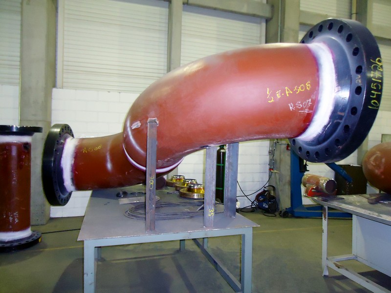
We call spool an
assembly of pipe and fittings like elbows, flanges, tees, etc., usually
terminated with flanges. Piping systems for process plants in general are
commissioned into two stages: the pre-fabrication of pipe spools and the site
installation. Some of the reason for pre-fabrication are limited space on site,
weight of components, weather independent production, better quality, higher
accuracy etc. On the down side they might not fit on site but all things
considered spools are widely used throughout the industry.
My background is
high quality, high purity water for medical, pharmaceutical and scientific
industry so I don’t deal with spools at all but Autodesk is really slow at
improving Tube and Pipe and I wanted to test the water and see what I can come
up with. Decided to see what’s out of the box, ignoring ilogic and other vb
scripts that could solve this mess.
In an ideal
world you would have each spool as a separate run so that BOM and Parts List
will indicate proper quantity but it’s not feasible to do ten thousands runs in
a single T&P assembly. Keep in mind that due to its weight a spool can be
just a flanged tee (think large diameters).
On this premises
I would do the whole T&P in a single Run, mingle them all in and control
the sizes by creating separate routes.
First solution:
Design View Representations.
I bet you’re
using this right now and there’s nothing new under the sun but I will present this
anyway because there might be some nice tricks you’re not using at the moment.
I like to do my
design view representations and level of details in a separate tab so open the
assembly, locate the run and right click open. For simplicity I will call the
assembly that contains the Tube and Pipe assembly “Main Assembly”.
TIP: You cannot create a design view from within the
main assembly for the T&P assembly or any of its runs so if you want to
modify design views you need open the files explicitly.
TIP: Saving runs
is only possible form the T&P assembly or any level higher but as long as
they are both open you can modify the files and then switch back to the T&P
assembly or any level higher (like the main assembly) and save the changes.
TIP: There is no Open option when right-clicking a
route in the browser so if you need to open it you can select it in graphical
window or the browser but right click on the graphical window to find the open
command.
With the run
open expand the Representations folder, right click the main view node and
choose new. Click twice on its name to change it something more meaningful.
Select your spool components and choose isolate from the right-click contextual
menu.
TIP: To quickly choose parts at any level down bellow
hold down SHIFT and in the right click menu choose Part Priority. Now you can
select any part no matter how deep it is buried in the level tree.
TIP: Another way of isolating components is to select
them and then hold SHIFT+right-click and choose invert selection to select all
other where you can toggle Visible off.
In the drawing
environment when placing the view select your design view previously created to
bring in a and display just those components.
The main problem
with this solution is the reported quantity and item number in the parts list.
While place a
parts list for your view you will notice that all parts are shown but we can
overcome this with a filter. Edit the parts list and choose Filter Setting, and
in the Define Filter Item drop down menu choose Assembly View Representation.
In the view representations choose the one you defined, click the green
checkmark then OK for the Filter Settings window and OK again for Parts List
window. Alternately instead of filtering for Assembly View representations you
could filter for Ballooned Items. The parts list will be empty until you start
ballooning your view and you will end up with same results only that you need
to have balloons for each item you want to show up in the parts list.


You will notice
that the quantity and item number will take into account the whole assembly and
furthermore the item number might be out of sequence. You can use the renumber
items function on the parts list but only if you detail each design view on its
own drawing. The item override is drawing persistent so creating separate
sheets will not work, and the changes on one sheet will modify all sheets so
you will end up with weird sequencing or duplicate item number.
As long as you
inform your fabricators that the quantity and the item number pertain to the
whole project you might want to use this solution.
Second solution:
iAssemblyes. (I can hear some eyes popping out).
Creating
iAssembly members is another way of documenting the spools and with better
results. Creating iassemblyes is not possible while editing the files from the
main assembly and once again you need to open the files explicitly.
Right click on a
run in the browser or graphical window and choose Open. On the Manage tab,
Author panel click Create iAssembly. This will create configurations of the run where each member will be a separate file
on disk. Right click on the Member column and notice that it’s marked as the
filename column. Specify different names for your members but you can have same
part number for all of them. Right click anywhere on row one, choose insert row
and setup your part number and member/filename values. Click OK when you
finished adding rows.
TIP: Use the Options button to setup sequencing and
auto fill in for your member, part number values.
Once you close
the iAssemlbly Author window you will notice a Table in the browser right under
Relationships folder. This will contain all the children listed by the Member
name. If you right click on the Table node you can choose:
-Delete (this
will convert the ipart/iAssembly to normal)
-New (to create
a new member)
- Edit table
(this will edit the table inside Inventor)
- Edit via
spreadsheet (will open in excel)
If you convert
the T&P assembly or a run to iAssembly, the Edit table option is grayed out
but all the rest will work and opening with excel will allow any operation like
deleting a member.
TIP: If you want to edit the table inside Inventor you
can click on Create iAssembly again from the Manage tab and it will bring up
the table editor even though the option is grayed out in the browser contextual
menu. Also, instead of creating the T&P files in the main assembly you can
create another subassembly in between (a container if you will). The edit table
will be available in here from the contextual menu or by double-clicking the
Table node.
As a general
rule if you have 3 spools then you need to create 4 members. The first member
you will keep intact and it’s used to show and document the complete assembly
while the other you will modify to show individual spools.
In order to
modify a member alone without changing any other you need to activate the Edit
Member Scope in the Manage tab, Author panel, Edit Factory Scope fly-out arrow.
Activate the
second member and after selecting all the components that are not part of the spool choose Exclude from the contextual menu.
TIP: You can do that really quickly by choosing the
spool parts and then hold down SHIFT + right-click and use Invert Selection.
Now you can click Exclude from the contextual menu.
Do this for all
spools and then save the file.
Open the drawing
and place a view. In the Drawing View place dialog switch to Model State tab
and choose the member you want to detail then click OK to place the view.
Placing a parts
list from that view will populate the table with only those components in the correct quantity as well. In the edit table window you can choose a different member to
report by clicking the Member Selection button. Here you can also notice that
Hide rows of zero quantity is checked. This is what hides the other members so keep it checked.
You can show the
number if items by adding Item QTY to your list from the column chooser menu
but DO NOT REMOVE QTY from the list
while in here because the Parts List will show complete assembly again. Click OK in the Parts List Column Chooser and then right click
the QTY column and select Column Width. Here enter a really small value like
0.1, click OK to accept and then Apply in the Parts List window.
This will hide
the QTY column from the Parts List but depending on where QTY column was in the editor window you
will see a double vertical line that you can drag left/right to show the column. Applying
the changes will show QTY column in the editor window but not on the drawing.
TIP: You can zoom the editor window just like in any
other program (adobe, web browser, explorer, office products) by holding down
CTRL and spinning the mouse wheel up and down. This will make it easier to show
the QTY column again.
So now we have
proper items reported with a proper quantity but the item number is still out
of sequence. Just like in the design view solution you can use the Renumber
Items function in the table editor. Keep in mind that these are drawing
specific so you need to detail each spool on a separate drawing rather than on
separate sheets.
And this is it….
Are you still awake?
Like I have
mentioned I am still experimenting with a different solution and I found a few
bugs that need documenting. I hope to have it ready for next post.
Video to follow..
Later,
ADS.