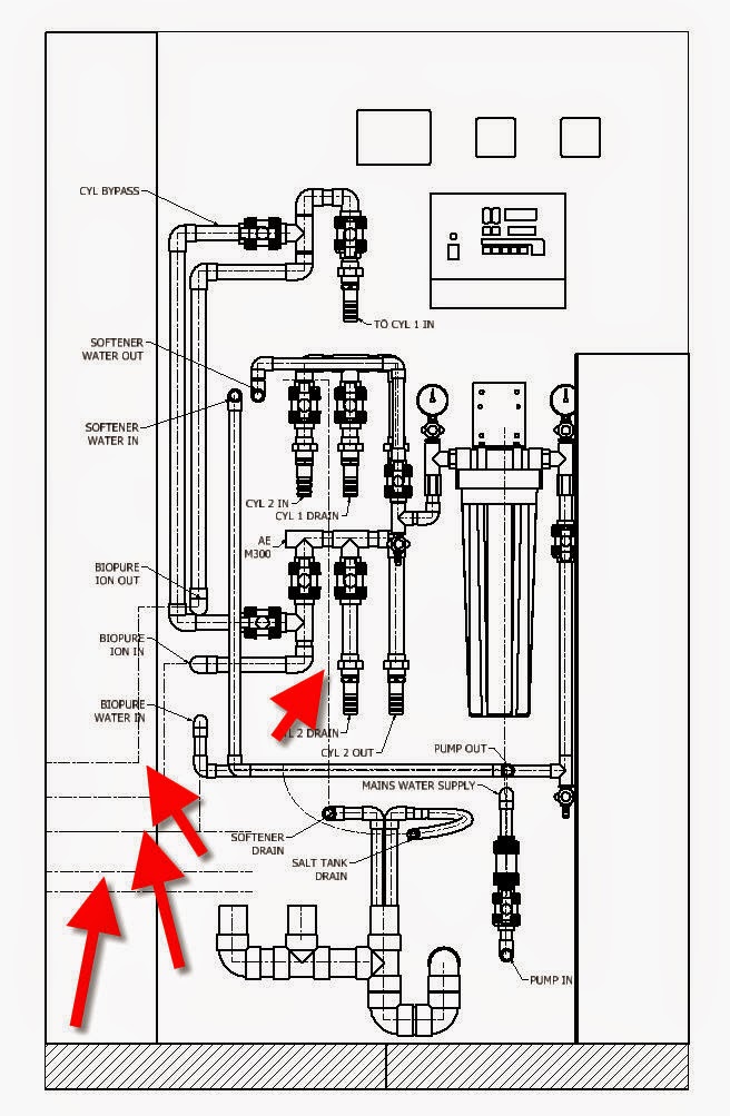
Showing posts with label Inventor. Show all posts

Friday, 23 December 2016

Fitting Alignment Issue

What’s wrong with these fittings?
 
Weird alignment

weird again.


My fitting orientation is all wrong.  You will get this especially on zero dead leg valves for pharmaceutical products but I’ve seen this on other products.

If you create a plane between the 3 connection points of the valve you will see that it’s not parallel with the rest of the geometry, valve body in my case.

default orientation

The direction is given by the 3’rd connection perpendicular to the line between the first and second. I think this is to help out with inexperienced users, idiot proof really, helping out if you didn’t align your connections to the model but that's just for straight fittings like tees.

Now what? Am I supposed to measure the angle every time and change fitting orientation on a continuous loop? (rolling eyes).

In order to fix this you need to add another authoring point and make it a 4 point connection.

4 Connections on a 3 point fitting? Are you mad?

I thought we already established that and we’re here to have some fun and solve some problems.

 We will be creating the 3rd connection inline (same plane) and parallel with the fitting as spare, never to be used and instead the 4th connection is to be used.

It might help to make the 3rd on a different plane away from 4th like right on the origin line just so it’s out of the way when placing or connecting fittings to it. We want to make it very obvious from the snap preview that it’s not the one to be used.

authoring dialog window

I have also gave it a really small connection size; a size we would never use like 1/8” to differentiate it even more and keep people from connecting to it.

And this is what the difference between placing a 3 or 4 connection fitting looks like
 
compare the results.
I’ve given this example before on autodesk forum on a similar issue.

You can keep just 3 connections if you align the third but we can do better.

3 would do but 4 is better


I feel it’s best to have a 4’th connection but be careful on placing fittings.

Watch out for ghost connection when placing this fitting. 

Later,
ADS


Wednesday, 21 December 2016

Punch iFeatures

You have no excuse!


iLondon
I will explain this one again and you will no longer have an excuse.

 You will have to force yourself and use it but trust me it will save a lot of time and increase your productivity.

I’ve seen this one too many and it’s killing your productivity and possibly your enthusiasm on using features, especially punch features.

First of all what are iFeatures?

Autodesk dictionary helps us out:
“Converts a single feature or a collection of features into a feature you can reuse in other part files.”

The definition is a bit circular, I agree. What that means is that if you model the same things everyday (keyways, for example) then you better make those an iFeature and reuse them.

Furthermore the iFeatures can have a table and you can generate custom sizes from easy to use forms with drop down menus and you can even have custom prompted values, with range and increment.

You will get a new file type "ide" but you can even drag-drop it from windows explorer.

I use them all the time and I have all sorts of ifeatures like flanges, ferrules, pipes, but especially features for my tanks and vessels, like manholes-manways, spray balls, feet, ladder attachments, lifting trunions, on and on...

One essential rule is to have the feature self-contained and do not reference any other geometry. If you do need to make it depended then only reference features to be included in the ifeature element.

 A special case are the Punch iFeatures for which the first element needs to be a sketch with a work point; this will be used as the insertion point and is especially helpful with recurring patterns.

We are here because you spent a lot of hours planning ahead, tested your ifeatures and perfecting the technique of making them independent and yet they fail to work. The work feature is not normal to the face and you have punches that are not protruding the sheet metal part.

And that is because your work is too perfect! That’s right, you need to take a step back, don’t make it quite that independent and reference the sheet face.

Typical procedure is to create a sketch and place a work point on it. Then create a construction line trough the point and finish the sketch.

Now you have the insertion point for your punch ifeature. You then create a work plane where you model the sketch of the punch.

The wrong way to do it is to create the workplane from the sketch workpoint and the sketch construction axis. At this point the ifeature will have no reference to the sheet face and it will spin in space as it sees fit.

Wrong way of doing it:


Wrong way of doing it

Correct way of doing it by referencing the construction line and the face where the sketch is defined.

Correct way of doing it

Don’t worry the face has been referenced before when you created the insertion point so you'll still have only one reference to pick when placing this.

Wrong way of doing it, end result:

Wrong way - wrong results

Correct way of doing it, end result:


Correct way - correct results

Repeat after me:
“I will use ifeatures from now on, save time and increase productivity”

 Later,
ADS


photo credit: @Doug88888 London - Light painting London (license)

Component Sketches Off


I hate when people don’t clean up their models. Although not right my mind associates this to a messy person with unclean desk, car, and garage, buried in piles of unneeded stuff.


                OCD is my middle name and while I hate this side of you, I love you as well and I think maybe you weren’t taught how to do it properly.

                I suggest you never use the “Object Visibility” drop down on the View tab.

I NEVER USE IT; except to see if you’ve been cheeky and got this quick fix like a drug addict.

It’s a crapshoot and it will bite you faster than you think. Have you considered the time, effort and stress you are going to experience when using this in large assemblies.

That’s all I am going to say and I will share  a bit of iLogic code I use to clean up this mess I see regularly with sketches not being turned off.

I have another one where I turn off the visibility of workfeatures, WorkPoints, WorkAxis, WorkPlanes and I like to keep it separate from the sketch visibility because when using it with tube and pipe it will turn the routes off and I don’t want that.

Component Sketches Off

I have also wrapped the whole process as a single transaction because if I need to undo the operation I only need to do a single undo not clicking back for each sketch that is off.


Code below and in this download link

-------------------------------------------
'catch and skip errors
On Error Resume Next
'define the active assembly
Dim oAssyDoc As AssemblyDocument
oAssyDoc = ThisApplication.ActiveDocument 

'get user input as True or False
wfBoolean = InputRadioBox("Turn all Sketches On/Off", "On", "Off", False, "iLogic")

' Process the rule, wrapping it in a transaction so the 
' entire process can be undone with a single undo operation. 
Dim trans As Transaction 
trans = ThisApplication.TransactionManager.StartTransaction( _ 
        oAssyDoc, "Sketches Off")

'Check all referenced docs
Dim oDoc As Inventor.Document
For Each oDoc In oAssyDoc.AllReferencedDocuments
    'set Sketch visibility
    For Each oSketch In oDoc.ComponentDefinition.Sketches
    oSketch.Visible = wfBoolean
    Next    
    
Next

'end transaction for single undo
trans.End 

'upate the files
InventorVb.DocumentUpdate()
-------------------------------------------


Later,
ADS
photo credit: Rubina V. Jahrmarkt (license)

Wednesday, 14 December 2016

RAL Library 2017

                Looking for RAL library? right place to be.

RAL library

                A while back I have posted a RAL appearance library and it’s been copied, shared, and spread all over, some crediting while others not but you can still identify your own work especially if you’ve done a mistake or two.

                While I don’t use it anymore I have been asked by colleagues on my previous company to see if I can migrate, update it to work with 2015 and now with 2017 so I’ve decided to share it once again for the greater good. Some people will take credit, not doubt about it but that’s life and not why we are here.

                Unfortunately it didn’t quite migrate as expected and I am seeing the colors a lot brighter in 2017 preview window almost as if they had self illumination, which I did check and it’s not.

Don’t be fooled by this, it’s only the preview thumbnails that have brighter aspects and the models will look right, and so the edit appearance window.

Small mismatch

                Use it as it is, good or bad it’s still better than renaming an existing color manually every time.

                This is especially useful in 2017 now that we can use the appearance as a reported property, in parts lists, bom, notes, etc.

                From the what’s new pages of AIP 2017

Appearance property
The model Appearance value is added as a selectable property. You can add the Appearance property to a bill of materials, or a parts list.


Appearance property

                While I can send the library and provided a detailed description on how to attach and use it, I feel it’s better if I just give you a part with all the appearances locally and you can copy it to your preferred library.

    Don’t you think so?

Almost forgot to share the link, that would have been useless ! 


Here is the 2017 part file.

Later,
ADS

Friday, 9 December 2016

Part Number on Flat Pattern

I’ve told you before I like helping out on Autodesk Answer Days and it’s good to keep an eye on that when it happens.


That’s when you get some of the best questions because a lot of people have done the research, know there is no solution available unless an Autodesk employee looks at the code and provide the insight or blends a quick bit of code for your problem.

As I am aware not all of you have the time for it I try and share the best, rare, exceptional that catches my attention

                Exactly this case for the question “How to get Part Number on Flat Pattern”.

                Seems we have covered this before and you are correct to think this but it was a bit different for we have showed how to do that from the drawing using a symbol note before the export; you can read it all again here.

                But this is different for what he wants is to have the part number on the flat pattern in the model and I am guessing that is because he wants to do emboss it, cut it out or just have it as a text on his flat pattern exports.

                You know you can export the flat pattern or just a face, right?

                Right click on Flat Pattern and choose Save Copy As with sat, dxf, dwg as output or right click on a face and choose Export Face As with dxf, dwg as output.

               
Flat Pattern Save Copy As..


Export Face As

                The solution is simple brilliant and Cai from Autodesk has provided the answer.  Create a sketch on flat pattern face with a text in it and the code bellow will change that text to Part Number. All you need to do is run the iLogic code and watch the magic taking place.
               
Dim oDoc As PartDocument
 oDoc = ThisApplication.ActiveDocument
 
Dim oDef As SheetMetalComponentDefinition
oDef = oDoc.ComponentDefinition
 
Dim oSK As Sketch
oSK = oDef.FlatPattern.Sketches(1)
 
osk.TextBoxes(1).Text=iProperties.Value("Project", "Part Number")

How good is that? Because I find it brilliant.        

         Of course the user needed some more; as it happens with this things and we jumped right back to help him out.

         What if there is no sketch on flat pattern? Can I prompt the user to create it?

         Cai replied:

If oDef.FlatPattern.Sketches.Count >0 Then
 oSK = oDef.FlatPattern.Sketches(1)
Else
 ' There is no sketch
End If


And I (late as usual) told him to use a try/catch; here is the complete code:


Dim oDoc As PartDocument
 oDoc = ThisApplication.ActiveDocument
 
Dim oDef As SheetMetalComponentDefinition
oDef = oDoc.ComponentDefinition
 
Dim oSK As Sketch
Try
    oSK = oDef.FlatPattern.Sketches(1)
    osk.TextBoxes(1).Text=iProperties.Value("Project", "Part Number")
Catch
    MessageBox.Show("Sketch not found" _
                    & vbLf & "Please crete a sketch first", "No sketch")
    
End Try


Later,
ADS photo credit: Panoramas Washington - National Gallery of Art - Calder - 8-11-2014 - 17h18 (license)

Thursday, 1 December 2016

Custom Elbow, Self Draining Lines P1

Self draining lines?

I’ve used those quite a lot on this past year and it seems we will continue in the ones to come.


I have been contacted by one of you (my internet friends) and asked if I think it’s possible to create custom length elbows and use it with Tube and Pipe.

                Apparently his company has open a support case with Autodesk and after a thorough investigation they were told it’s not possible and to continue constraining the fittings, one after the other just as they do now.

                So he has resorted to the dark side and contacted a bogus blogger to see if he has a possible solution. Happy to say I do have a possible solution but it’s up to him to decide if he wants to go the TP way.

                The biggest challenge is to create an elbow with custom angle and where the user is prompted to specify a length for the entry, exit legs (straight section of the elbow).

                Most important phase in the design process is to get the user requirements right and I have failed that from the beginning but I’ll blame the language barrier and the different time zones.

                All the companies I know buy 90deg elbows and they bend them to required angle because it’s cheaper this way. My initial impression was that they use 90deg elbows as well but they cut the legs at an angle (slope angle) rather than bending the elbow.

                Some good info emerged out of this and that’s why I decided to mention it. So keep it in the back of your mind in case you ever need to do something similar.

                There are a couple of methods to cut the legs back but some will give you errors down the line.

                Do not control the leg lengths by editing the sweep path because when removing the leg altogether (max cut) you will get errors on generating other members with 0 length legs.

                Do not author the part by using the leg face because that will fail. I will fail when you cut the face to an angle (the face is not circular anymore) and it will fail if you remove the straight leg completely, (face not existing anymore).

                Instead create sketch points and work points for your authoring connection setup.


Authoring work features

                While the elbow is 90deg the connection needs to be picked up as different angle, that is a must for self draining lines or you will not be able to select the fitting in the TP Style Setup dialog window.


Authoring angle


TP style dialog
                For that you need to create custom work axes but that’s easy if you create some construction lines in the sweep sketch. Check out my blog on authoring empty parts here.

                Because I wanted the users to have a minimum, maximum allowable distance and a 1mm increment (keep it nice and tidy) I have setup custom cells for my ipart table and that was a big waste of time.

                Do not create custom range cells or columns in the ipart table; they have no effect once published to content center. Instead publish it as it stands and alter the content center family table.


don't waste time here

                Now that we got that out of the way I will show you what my friend really wanted and how to create a proper custom length elbow to be used for tube and pipe self draining lines but that in the next blog.

                PS: I am doing a video for this as well…… more than a year since I’ve done a video !!!!

Here is the test elbow (the wrong one) in case you are looking for inspiration or just want to test it out.

Later,
ADS


photo credit: Hernan Piñera Seated (license)

Friday, 21 October 2016

Drawing layers

                Do you use layers in Inventor drawings? Or do you consider them legacy, obsolete, pre cretaceous kind of animal?

Add caption

Last week we looked at showing hidden lines for buried components and now we look at a different method for doing that but with the additional benefits.

                When detailing pipe routes you can use the “Include Route Centerlines” command but if that view is a detail, section, cropped view you end up with a lot of extra lines. You can use this method to clean them up as well.
Include Route Centerlines, adds more than visible.
               

                Another good example is the worm gear bellow. I have an M10 hole on center and I can’t really show it properly. Top left to bottom right I have hidden lines view, normal view, hidden break out view, normal breakout view and yet not of them looks good enough.

Top left - Hidden Lines, Top Right - Normal,
Bottom Left - Hidden Break Out, Bottom Right - Normal Break Out

                What I tend to do is turn the hidden lines on for that view then edit the layers, where I turn off every one of them except Hidden and Hidden Narrow and save the style. Now I only have left the hidden lines which makes it so much easier to delete the extra stuff.
               
Turn layers off to help your selection.

                TIP: On the edit layers dialog window you can SHIFT select them all and when you click the light bulb the visibility changes to all at once.

                TIP: It’s much easier to do a window selection and select all and then hold down CTRL and deselect the view, and other curves that you need keeping. You can then use the Visibility on the right click menu to turn them off at once.

                And there you have it. Hope you’ll put this to good use and give layers a chance ; they are not used just for AutoCAD exports only.

Later
ADS


photo credit: Eugen Naiman layers (license)

Thursday, 13 October 2016

Drawing Hidden Lines

In the drawing have you ever needed to show components buried down below?


I didn’t have a lot of time this week for blogging but I forced myself to wake up early today and write a couple of words on this trick I use quite a lot. Will try and keep it simple for now and will do a follow-up next week on layers and how to leverage them to your advantage.

                A lot of the times I find myself in need to indicate components that are not visible unless you change the view to hidden lines. That can be daunting for untrained eye to look at and it will clutter the drawing so I tend to avoid it if I can.
               
For example take a look at the vessel in the image bellow. Turning the view to hidden lines would have made a mess out of it with no way to identify what’s what. Showing just the legs in hidden lines makes a huge difference.

Hidden lines accentuate design.
To show a component you need to find it in the browser, right click, and choose "Hidden Lines".

Enabling hidden lines

As soon as you set hidden lines on you get a message saying "Dependent vies styles will become independent”.

Changing the view message

Sometimes the “Hidden Lines” menu will be grayed out and that is because your view has linked design view representation. For that you need to edit your view and tick the “Associative” box off as bellow.

Associative off on view properties

A new option is needed here besides “show hidden lines” and that should be simply “show” which will turn the model visible (in dotted lines because it is underneath in the background) without its internal geometry. I need to indicate the component in outline, not the whole geometry but that’s for a latter post.

Next new feature?
   
Take a look at the drawing below. The drain header is visible and I only need the outline body; normally we show all runs in hidden lines but this is just a sales proposal and I couldn't be bothered. This shows just enough info, eliminating clutter and accentuating design.

Way better, isn't it?

Later,
ADS


photo credit: Max Garçia Metallica (license)

Friday, 7 October 2016

T&P Hoses P2 - Documenting Hose Lengths

How do I show hose lengths? How to document hoses? I need to document cut lengths, swage distance as well as overall lengths, so how to do that?


                Last week we covered BOM structure for hoses and I’ve showed you how to mark them as single items in BOM / Parts List. This is useful if you don’t’ manufacture the hose and you don’t need to show all the sub-parts individually.

                But what if you need to show those dimensions and send the drawing over to whoever is going to manufacture it; assuming it’s not a standard stock item.

                Hoses are created as a subassembly in tube and pipe and you get the route, the sweep part and the connectors (depending on style settings) in one single assembly.

Hoses are created as assemblies

                Unfortunately the info is not at the assembly level and it can’t be exposed when changing BOM structure to “Purchased” or “Inseparable” (check my previous post here). All the info is created in the hose part (the one containing the sweep).

                If you open the hose and check the parameters window you can find a couple of parameters defining the various lengths for the hose (they are exposed as custom iproperties as well.)

                If you open the parameters window here’s what you will find:
PL - Pipe Length (hose in this case)
RPL - I believe this is "Rounded Pipe Length" (hose in this case)
OPL - I believe this is "Overall Pipe Length" (hose in this case)
ROPL - I believe this is "Rounded Overall Pipe Length" (hose in this case)

Parameters exposed to iProperties.

If you have connectors each end (like I do) you will notice that the sweep sketch is made from a spline and 2 straight lines (swage distance). Measuring the spline and the individual lengths you will get PL(hose length) which is then rounded to the nearest increment (changeable from the T&P route style) and you then get RPL (rounded hose length).

Rounded increment is declared in the Route Style

OPL (overall hose length) you get by adding the connector lengths to the PL (hose length) and just like above when you round this to the nearest increment you get ROPL (rounded overall hose length).

                If you need this info in the Parts List you need to add these custom iproperties manually by editing the drawing table. However if you marked the hose as “Inseparable” or “Purchased” the info will not show up.

                In both cases you can add a Leader Line and use the “Custom Properties – Model” to show these on the drawing.
Use Leader Lines to document the various lengths
                Here's a short animation of the process.


Later,
ADS photo credit: Garden hose (license)

Monday, 3 October 2016

T&P Hoses P1 - BOM Structure


Do you include hoses and flexible tubing to your design? Are you thinking into taking your products to next level by adding this info to your design?


While we use them in our plant layouts we don’t really document them on the drawing but nonetheless there are some good practices as well as tips and tricks.

Will keep this simple and split it into separate blogs and for now the question is:

How can I show a hose assembly as single part?

We are not hose manufacturers so it would help to see the assembly in the Parts Only section of the BOM along with all the fittings, valves, conduits, all parts really to be purchased.

This needs editing the BOM and changing the “BOM Structure” field to one of these 2 options:

- Mark it as “Purchased”

-Mark it as “Inseparable”

For all my life I have been thinking about “Inseparable” items as welded, casted, glued, press fitted, riveted kind of items but it’s really just a way of grouping several parts in BOM.

“Purchased” it’s what I’ve been using and it’s a nice way of merging multiple parts as a single item. Think of skids, tanks, etc. or any assembly which you vendor has sent over and you consider that a single purchase / single item.

The advantages of keeping it or importing it as assembly rather than single part is you can play with Level Of Detail (LOD), Design View Representations or show different positional representations.

 In the Structured tab you can still expand and collapse it (if show all levels is active), edit the iproperties but now it shows up in the Parts Only section of the B.O.M.

At this point should mention that if you want to show the child components of the hose assembly you will change the BOM Structure to “Phantom”. This will promote the children and hide the subassembly; I use this all the time to group things together for less constraints, improved pattern, etc.


Changing Bom Structure type.
Later,
ADS


photo credit: Steel-braided hose (license)